Archive for the 'Boards and Systems' Category

August 19th, 2023 ~ by admin

Dead Brands of Computing Past: Soltek

This is the beginning (hopefully) of a series of articles dedicated to dead brands – computer hardware manufacturing companies, which at one time enjoyed overwhelming success, but disappeared for one reason or another (some could not stand the competition, some were mired in corruption, some simply could not rebuild their own business). This first article will look at the story of the smashing success and unpredictable collapse of the Taiwanese MoBo manufacturer Soltek Computer Inc., one of the leading motherboard manufacturers in the early 2000s.  (EDITOR: I Can’t wait for Abit – all hail the BP6)


When you are a monopolist in the market of goods or services, then you are not afraid of any competition. But what if young, ambitious players, trying to surpass you, offer the market something that is not inferior in quality, but at the same time allows the consumer to save money? In such competitive conditions, you can either recapture positions, choosing innovative paths, or leave the pedestal. We saw similar races in the global IT market at the beginning of the twentieth century. Along with predatory companies in the unpredictable ocean of computer hardware, myriads of small manufacturers of computers and components multiply and multiply. And if someone does not manage to grow from a small fry into an adult fish, then this is a very common phenomenon. It is impossible to say that only fierce competition is the main cause of loss of profitability or absolute bankruptcy. The history of market relations knows many examples of how, due to negligent management, venerable brands burst like soap bubbles. There were cases when professional marketing was not enough to promote an innovative engineering idea. Often, the reasons for the collapse of brands were global economic and technical realities.

MoBo manufacturers specializing in the manufacture of motherboards, after the standardization of Intel microprocessors, popped up around the world like mushrooms after rain. In the mid-90s of the twentieth century, a personal computer still remained an individual assembly electronic device, and everyone could choose their own set of hardware, based on the needs for the functionality of the PC system. In the same period, it became absolutely clear that the IT technology market is an unplowed field. Go ahead, plant your own “seeds” and earn fast-growing profits. Thus, a relatively constant circle of microchip manufacturers gradually formed, which, with enviable regularity, introduced new products to the electronics market. By this time, the technology of surface mounting of printed circuit boards (the so-called SMT technology) was established, implemented using pick-and-place class robotic mechanisms. It has become the driving force behind the multilayer printed circuit board industry. Another important point in the rapid development of the IT market was the cultivation of young engineering personnel who offered not only innovative developments, but also the rapid implementation of competitive products. It goes without saying that the appearance in 1996 of a Taiwanese manufacturer – Soltek – did not make such a splash.

The new player boldly rushed into battle: the company’s production facilities were based on the use of the latest SMT equipment, and the staff consisted of the most talented personnel in the field of computer engineering. The head office of the company was located in Taiwan’s His-Chih Industrial District (Xizhi District). The area is known for being the headquarters of brands such as Acer and DFI. The company’s first assembly line was also located in the area. After two years of trademark paperwork and invention patents, the U.S. Patent and Trademark Office has registered the Soltek™ brand with ownership of Soltek Computer Inc. A trademark slogan was also registered: Soltek – The Soul Of Computer Technology. Main activities: computer technologies, software systems and products of research activities in the field of IT. But this is only a general nomenclature, while the detailed list of Soltek products was quite wide, from PC motherboards to keyboards and mice.

SL-54U5 Super 7 Board

The products of the first production strategy are low-budget MoBo solutions based on VIA chip technologies, adapted for Intel and AMD processors. Consumer interest was captivated not only by the price of Soltek motherboards, but also by an extended set of interface capabilities of peripheral equipment, as well as a well-chosen set of utilities supplied in the kit.

Read More »

October 19th, 2022 ~ by admin

Soviet Argon-11S Computers for Space

Saturn-V

The launch by the Soviet Union of the first artificial satellite of the Earth and the first man into space was a real shock for the United States, raising the question in the eyes of the whole world whether the United States is really the leader of world technological progress. Moreover, not only American elites, but also ordinary citizens felt deeply wounded. A month and a half after Gagarin’s flight, US President John F. Kennedy announced the launch of an ambitious lunar space program. On September 12, 1961, Kennedy addressed the nation, calling for a manned mission to the Moon at any cost.

This is actually the first and main reason for the Americans’ success – their lunar mission program became a single “national impulse,” for which no effort or money was spared. At the same time, the Soviet Union accepted the challenge posed by the Americans rather “out of inertia,” as a response to their lunar program. Moreover, by that time the USSR had proved what it wanted, and there was no urgent need to be the first on the Moon anymore. Initially, the Moon landing was not part of the Soviet space program. In the late ’60s and early ’70s it was planned to build a large orbital station and a spacecraft for an expedition to Mars and Venus. Officially, the Soviet lunar program did not begin until 1964.

The key point of the lunar mission program was the development of a super-heavy launch vehicle capable of accelerating a craft weighing several tens of tons to the second cosmic velocity (aka escape velocity). In the U.S. NASA began to create a family of rockets known as Saturn. Although unofficially, NASA began to think about the Moon in 1960, even before Kennedy’s speech, and were working on various options for heavy launchers. The name “Saturn V” hints that the launch vehicle was the fifth model in the family. There were other options, even heavier than Saturn V, with some being planned for a Mars mission as well.

The question was who would build it. The chief architect of the Saturn V, Werner von Braun, chose the division of labor. This allowed him to choose the best of the best in the whole industry. He was able to use the most experienced people from each of the companies. For contractors, the decision meant big orders, not a huge order for any one. In the end, the main share was distributed among three companies: Boeing, North American Aviation and Douglas. All in all, more than 20,000 contractors and subcontractors were involved in the production of the rocket.

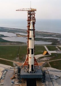
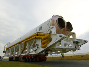
The first launch of the three-stage Saturn V rocket took place on November 9, 1967 and showed its amazing capabilities. The 3rd stage with the Apollo unmanned spacecraft and the lunar module mass-dimension model with a total mass of 126 tons entered orbit. And thanks to the sixth launch, humanity took a “giant step” toward the first landing of astronauts on the Moon. On July 21, 1969, astronauts Neil Armstrong and Edwin Aldrin made their first ever landfall on the surface of a natural Earth satellite. The Saturn V rocket still amazes today with its grandiosity. With a launch weight of 3,000 tons, it has a height of 110 meters, making it the tallest rocket in the history of world astronautics.
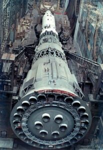
N1 Business end

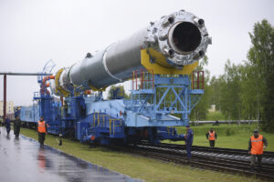
What about the USSR? In the Soviet Union, work on N1- a superheavy launch vehicle, began back in 1958. As noted above, it was originally created not to provide flights to the Moon, but to build an orbital station, as well as to launch interplanetary expeditionary spacecraft modules into orbit. Later, however, a belated decision was made to include the USSR in the “lunar race” with the delivery of a man to the surface of the Moon. Thus, the N1 rocket program was accelerated. Before determining the final scheme of the launch vehicle, the creators had to evaluate at least 60 different options. They decided on a scheme with spherical tanks for fuel and oxidizer, as well as a load-bearing outer shell, which was supported by a power set and circular placement of the rocket engines in each of the stages.  The First stage alone had 30 engines, which is a plumbing nightmare (as SpaceX is working out with their Starship launch system)

The stages of the N1 rocket were connected to each other by special transition trusses. The rocket complex, which included the launch vehicle H1 and the lunar system to send to the lunar surface with the subsequent return to Earth of a crew of two (the moon landing involved one person) was designated as N1-L3.

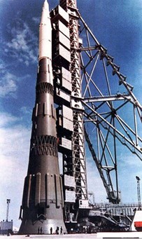
The N1 was never static fired, this led to issues being discovered at launch that would have been easier to catch without destruction if it had been

Getting ahead of myself, I will say that none of the launches of the N1 heavy launcher were successful.

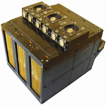
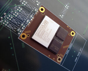
Onboard computer “Argon-11S”.

While the designers were trying to correct the mistakes made in the design of the N1 rocket, the technique of flights to the Moon with a return to Earth after a ballistic flight around the natural satellite of the Earth was being worked out. There have been launches of the Zond spacecraft series using the Proton launch vehicle. These spacecraft were an unmanned version of the two-seater manned spacecraft. All work was carried out in conditions of high secrecy. But now we can say for sure that the Zond-6 and Zond-7 spacecraft were controlled by an onboard digital computer. The Argon-11S.

It consisted of three functionally autonomous computing devices with independent inputs and outputs, interconnected by channels for information exchange and synchronization.


Fixed-point representation. Data bus -14 bit, commands – 17 bit. Number of commands – 15.
Execution time of operations (µs): addition – 30, multiplication – 160.
RAM capacity was 128 14-bit words, ROM capacity – 4096 17-bit words.
Weight 34 kg

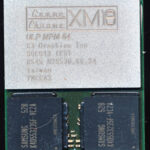
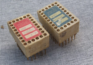
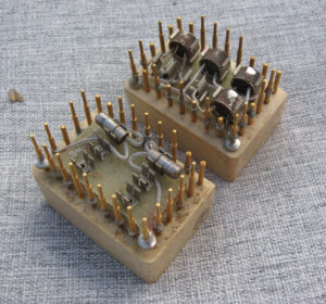
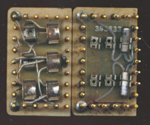
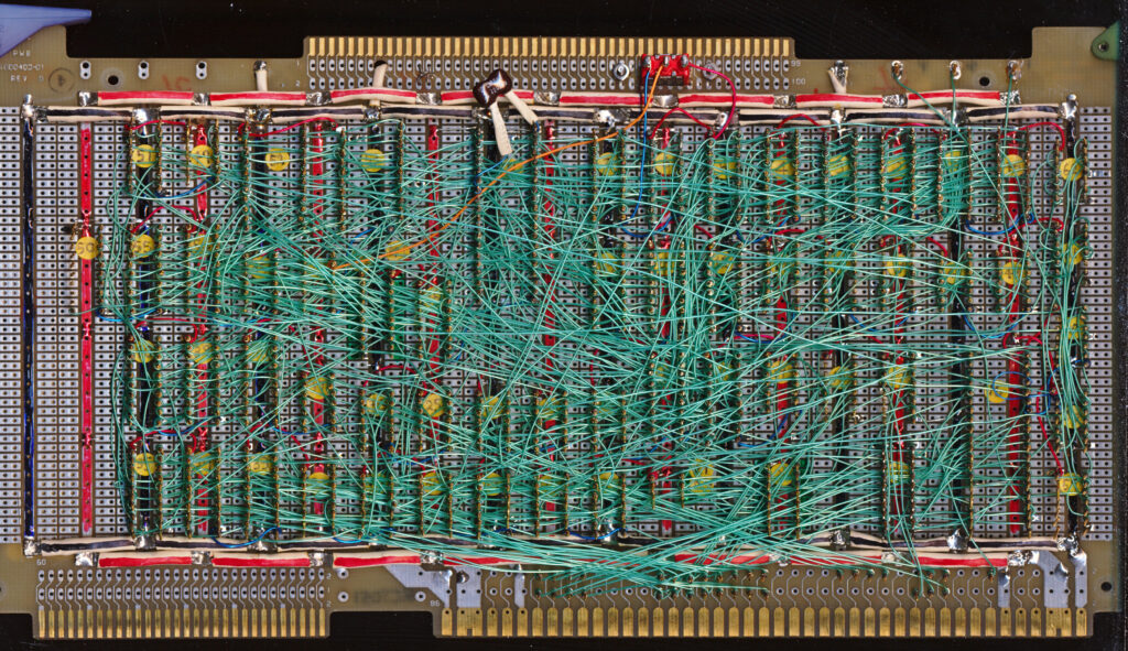
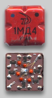
Element base: integrated hybrid microcircuits “Tropa-1”. The microcircuits of small integration degree are made on thick films and form a system of logic elements with direct links (OR, OR – NOT, AND – NOT, etc.). Microcircuits are made in the square metal-polymer case of size 11,6 x 11,6×4 mm, weight of microcircuits is not more than 1,5 g.

These were very similar to IBM’s SLT architecture for the System/360 mainframes in the USA at that time period as well.

Historically, these were the first integrated circuits developed in the Soviet Union. The active elements were shell-less transistors. The first prototypes of the series were named 1MD1-1MD6, 1MM1-1MM3. Hundreds of logic circuits were mounted on printed circuit boards and bundled together like a book.

Structurally, Argon-11S consisted of three identical functional blocks operating in parallel and independently of each other. The inputs of each block received exactly the same information from many telemetry sensors. On its basis, each block produced more than forty control actions. For the first time in the practice of creating onboard computers, a node redundancy scheme was applied. The final control actions were formed according to the majority principle. That is, if they were the same on two of the three outputs and different on the third, the values generated by the majority were taken as the basis. In fact, Argon- 11S was constantly voting for the most correct control action.

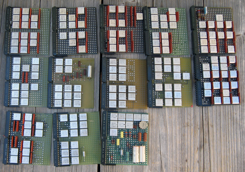
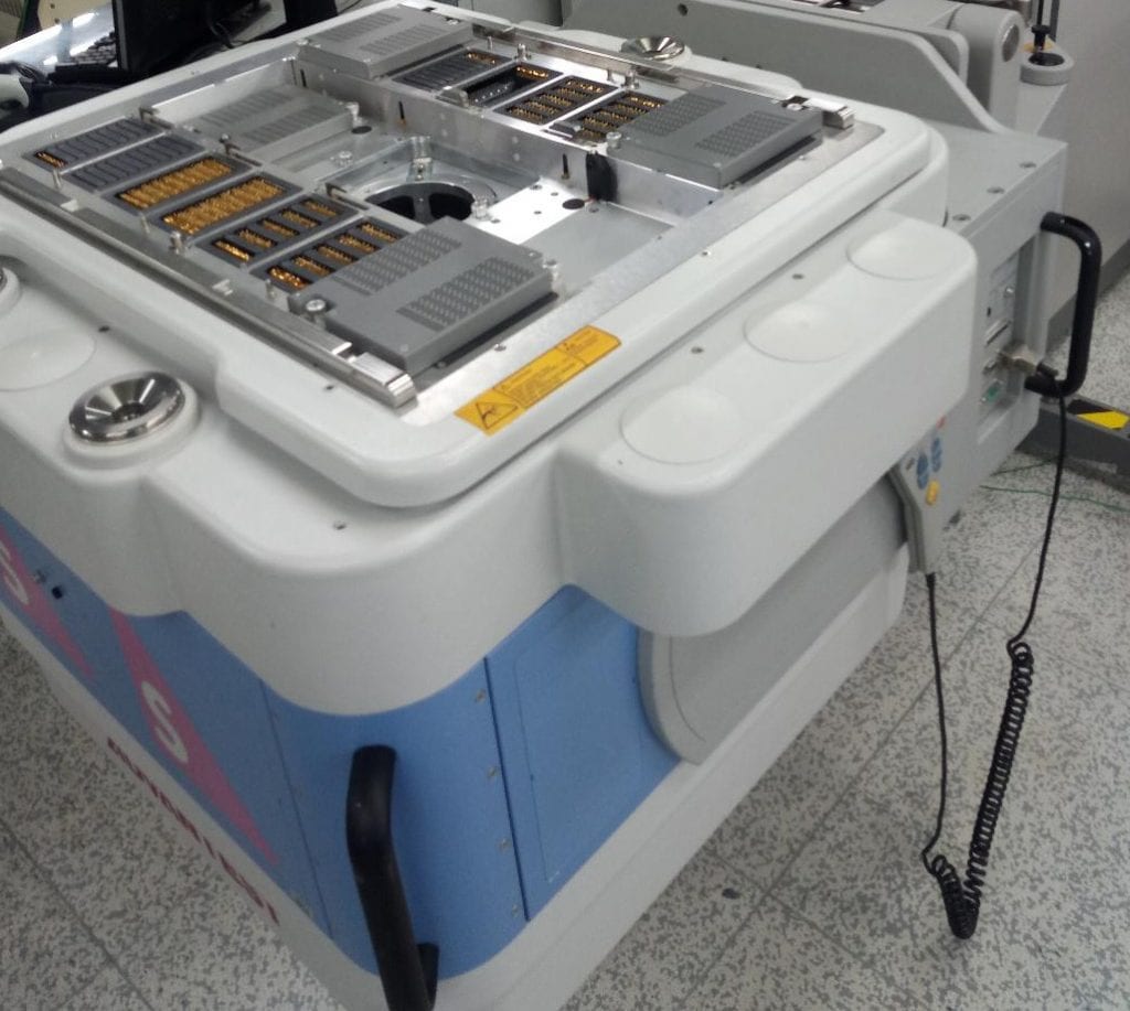
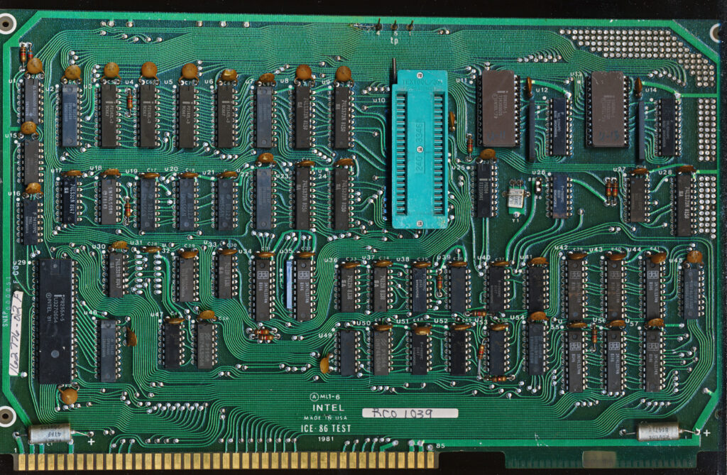
Various IBM System/360 cards showing similar technology at the Soviet Tropa series.

Zond-6 was the ninth launch of a prototype spacecraft. The purpose of the mission was an unmanned flight and photography of the Moon, the return of the lander to Earth with a landing in a given area, as well as practicing the functioning of the manned spacecraft in automatic version. Unfortunately, due to malfunction of the parachute ejection equipment, the vehicle crashed. After the failure of the Zond-6 return to Earth, Zond-7 was launched to the Moon on August 8, 1969. The day after the launch, the spacecraft maneuvered on an intermediate trajectory and obtained color photographs of the Earth. On August 11, the spacecraft flew around the Moon at an altitude of 1,985 km and conducted two sessions of photographs of the Moon and Earth. Zond-7 returned to Earth on August 14.

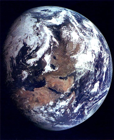
After a normal dive into the atmosphere, it landed successfully. The photograph taken by Zond-7 is less well-known than the Blue Marble taken by the crew of the Apollo 17 spacecraft, but it is no less beautiful.

This photo ended up on the mail block dedicated to the flights of these spacecraft.

It must be said that not everything was smooth with Zond-7. Prior to this success, there were three high-profile failures. Three rockets (two of them N1 and one Proton) with similar spacecraft exploded on the launch pads.

Despite the fact that none of the N1 rockets managed to complete the launch program, the designers continued to work on it. The next, fifth launch was scheduled for August 1974, but did not take place. In May 1974, the Soviet lunar program was closed, and all work on the N1 ceased. Two rockets ready for launch were destroyed.

Antares 100 series flew 3 times with NK-33 engines, the 4th flight was unsuccessful and resulted in a large explosion.

Only 150 engines of the NK-33 (the successor of the original NK-15 for the first N1s)  type manufactured for various stages of the rocket were saved from the N1. These engines had a chance to fly already in America. They were used in the first stage of the Antares 100 series launch vehicle of the Orbital Sciences Corporation (Now Northrup via Orbital ATK).  They also continue to be used on the Russian Soyuz-2.1v rocket, with the latest launch in April of 2022, still using engines built in the 1960’s, albeit with more modern electronics.

Soyuz-2.1v

Having lost the “Moon Race”, the Soviet Union concentrated its efforts on other projects that had a less prestigious, but no less important role in space exploration – orbital stations, as well as a fairly successful science campaign exploring Venus.  Hopefully in the next few years we will be able to see another truly massive rocket, with 33 engines on the first stage, launch, heading to the Moon, Mars, and beyond
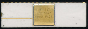
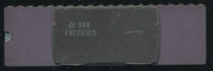
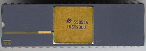
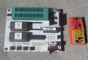
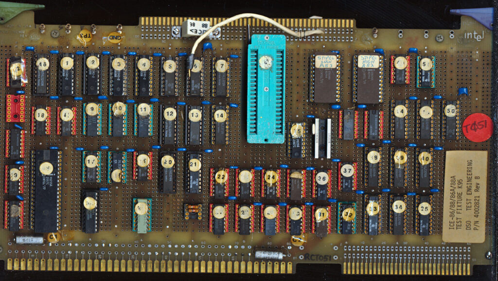
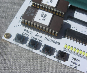
Posted in:
Boards and Systems

September 14th, 2022 ~ by admin

The History of the SUPER HEDT x86 PC

Introduction

Last time we talked about the history of the development of high-end computers or High-End Desktop PC (HEDT). In the discussion of the article, some readers remembered motherboards that belonged to HEDT, but were one step higher, both in terms of their technical characteristics and in terms of the cost of ownership of the entire platform based on them. It is possible to name such very high-performance systems – Super HEDT, which often also had their own personal names, and we will talk about them this time.

Last time, the date of the appearance of Intel processors for LGA1366 and the announcement of the first motherboards for them was taken as the beginning of the countdown for the announcement of the HEDT platform. This event happened in the fall of 2008. The reason for the appearance of such platforms was dictated by the decision of the main chipmaker to create two platforms: one for all consumers, and the second specifically for enthusiasts who are ready to get additional performance and new features for extra money that were not available (or needed) for owners of conventional desktop platforms. The logic of making such a decision is simple and logical, but with Super HEDT platforms things are somewhat different.

There may be several reasons for the emergence of such platforms. One of which is to show a competitor that we can do even it better and even faster, to make performance extremes, at the cost of incredible efforts of engineers and, as a result, an incredibly high final price for the end user. Although, for such systems, the price, although it plays an important role, is not a deterrent, because there will always be enthusiasts who are willing to pay as much as the manufacturer dictates to have the very best.

By announcing such a platform, the manufacturer can be sure that the fame and success of his Super HEDT platform will smoothly spill over to his other products, even in the budget segment, because if he is capable of producing a Super “miracle” of engineering, then all of his products, will also have the same properties as the miracle ones, only they will be slower performance and a reasonable price. Super HEDT aura and advertising will do their job and competitors will be forced to return from heaven to earth, because they will have nothing to answer.

The second reason for the appearance of such systems may be for a diametrically opposite reason –  when the manufacturer fails to defeat a competitor on his football field and the only way out is to continue the game somewhere in the orbit of the planet, where the opponent will definitely not fly. Your own personal field – your own rules, even if the price of such a decision will also be cosmically high and beyond the reach of most earthlings. But they will talk about such a decision, though not for long, but long enough to lift you up onto the podium of media fame for a brief time..

And oddly enough, the first Super HEDT system recalled in this article will be the system that was born according to the second, more pessimistic scenario. Has anyone already guessed it?

To find the answer to this question, we will have to go back in time to the very end of November 2006. At this time, the golden years of AMD had already passed, the dominance of its extremely successful Socket 939 and the fastest single-core processors, which included the various Athlon 64 FX’s, had ended. With the introduction of new revolutionary Intel Core processors to the market, AMD had been cornered with its Socket AM2. The market turned towards multi-core, and AMD had nothing to boast of in performance per core. The appearance of the first quad-core Intel Core 2 Quad processors completely deprived AMD of any chance for worthy competition.

If you look at the range of processors available on the market in the fall of 2006, AMD had different Athlon 64 X2’s, manufactured according on a rather outdated 90 nm process technology, the fastest model was the Athlon 64 X2, 5200+ with a real clock speed of 2.6 GHz and a processor for ” green” enthusiasts, the Athlon 64 FX-62 with a clock frequency of 2.8 GHz and a recommended price of $1031. At this time, Intel was selling the Core 2 Duo E6700 with a clock frequency of 2.66 GHz and a recommended price of $530 and a dual-core flagship Core 2 Extreme X6800 at 2.93 GHz, 1066 MHz FSB and 4MB of L2 cache. The cost of all Extreme Editions then was $999. But in November, Intel got its first 4-core processors based on the “Kentsfield” core. The Intel Core 2 Extreme QX6700 was clocked at 2.66 GHz and became the first halo chip, and then more “popular” models followed to conquer the market. The “Kentsfield” core itself was not an honest “quad-core”, it consisted of two Core 2 Duo cores placed on the same substrate. (Hello to all chiplets, and a separate AMD Ryzen) Well, AMD did not go well with its Phenoms, but something had to be done, at least for the sake of media noise.

Core 2 Extreme X6800

The recipe for such an answer is always the same: let’s take our server platform, embellish it a little, adapt the BIOS for enthusiasts, and give the server processor a free multiplier. We will make the number of sockets more than one and the answer is ready. But server systems have a lot of limitations, besides, some of them are hardware-based and cannot be adapted to desktop standards. But in such cases, there is no time for compromises, it is better to sacrifice functionality, performance will not suffer much from this.


AMD Quadfather

Read More »

Posted in:
Boards and Systems

July 14th, 2022 ~ by admin

The History of the HEDT x86 PC – Part 2 – AMD

AMD’s debut in the HEDT market

Part 2 of the History of the HEDT – See Part 1 (Intro + Intel)

2017

The debut of the AMD High-End Desktop platform happened in the fall of 2017. For his main competitor, he was unexpected and even shrouded in some mystery. In March 2017, the first models of the AMD Zen microarchitecture processors appeared on store shelves, they were the first Ryzen, where the flagship was the 8-core AMD Ryzen 7 1800X, priced at a modest $499. At that time, Intel’s flagship in the desktop segment was the Core i7-7700K, which belongs to the Kaby Lake microarchitecture and had only 4 cores capable of processing 8 threads. The cost of the Core i7-7700K was then $350. The new six-core new flagship Coffee Lake microarchitecture Intel Core i7-8700K would only appear six months later at a price of $370.

AMD planned to release processors with the ZEN microarchitecture for the desktop, mobile and server markets, it did not originally plan to release HEDT processors.

The appearance on the market of AMD Ryzen Threadripper processors has been shrouded in mystery. According to one version, the merit of their appearance lies with the enthusiasm of a small group of AMD engineers who, in their spare time from their main work, experimented with creating a high-performance processor that could be even more productive than the desktop Ryzen. A group of enthusiasts have been working on this project for about a year, and at the end of the work they presented their developments to the company’s management, which, in turn, considered them promising and allocated the necessary funding for commercial development.

Socket TR4

Until May 2017, no one knew about the work on these processors, which would then be called the Ryzen Threadripper. In August 2017, the long-awaited announcement of the first HEDT platform from AMD with three models of AMD Ryzen Threadripper processors happened. The processors were installed in the new TR4 socket with a crazy number of contacts at that time, 4094 contacts. The most basic Ryzen Threadripper 1900X ran at 3.8 GHz, had 16 MB of L3 cache, and had 8 cores capable of processing 16 threads. Such a processor cost $549. The average was the Ryzen Threadripper 1920X with 12 cores and 32MB of L3 cache. Such a processor cost already $799. Twelve-core HEDT competitor from Intel with thermal paste under the cover – Core i9-7920X cost $1199. The flagship of the entire HEDT line from AMD was the 16-core Ryzen Threadripper 1950X, which was estimated at $999. Intel’s 16-core counterpart, the Core i9-7960X, was offered to enthusiasts at a price one and a half times more expensive, for $1,699.

What did AMD’s first HEDT platform offer to wealthy enthusiasts?

Read More »

Posted in:
Boards and Systems

July 11th, 2022 ~ by admin

The History of the HEDT x86 PC – Part 1

Introduction

In this article, I would like to recall how the history of high-end computers or High-End Desktop PC (HEDT) began, what we now have in this segment, and what awaits us in the near future.

Until a certain point in time, the computer market for personal computers was not divided into subcategories. There was the concept of a personal computer, where its main criteria were: performance and cost. The higher the performance, the more expensive such a PC was. There was and still are ‘Workstation’ class PC’s but these are really more of a Business class (think CAD or Video editing) then what you would buy for your house. The problem of insufficient performance was solved for a very long time with the help of overclocking and it would seem that this order of things suited everyone.

If you want a faster video card or processor, buy the Top model. Until a certain point in time, everything was like that, but at the beginning of the 2000s, processor manufacturers realized that there was a certain group of buyers who were willing to pay more. Then they were called “enthusiasts”, and now they have been renamed “gamers”. Since 2003, Intel, in unison with AMD, has been releasing their processors for wealthy enthusiasts. The first processor model from “blue” was the – Pentium 4 Extreme Edition with a clock frequency of 3.2 GHz and a very nice price of $999 (A Celeron of that era was around $100 for 2.5-2.8GHz).

Thus, in this processor model, a beautiful and memorable cost, a defiant name and technological sophistication, the roots of which go deep into the server segment, are combined. The owners of the “extreme desktop processor” already considered themselves a completely different caste, and no overclocking of the older processor model could give an ordinary user the performance that an enthusiast had, and after all, extreme processors were also overclocked.

At first, AMD generally went the other way, a special separate platform was created for enthusiasts, where processors with their own separate socket were installed. Thus, the segmentation of the personal PC class took place at the physical level. We are talking about AMD Athlon 64 FX processors, and to be more precise, about the first model of this family – AMD Athlon 64 FX-51. I would call them timeless classics, still using a ceramic package, a separate socket, and special registered DDR-SRAM memory.

The release of these desktop processors for enthusiasts also marked the beginning of a new 64-bit era and changed the leaders of the processor industry. The yellow jersey of the leader shone on a green “background”, and Intel moved into the camp of catching up. As revenues and the image component of users and enthusiasts grew, marketers and simple engineers did not sit idly by. Performance is never enough (although it seems to me that for the last 5 years it has definitely been enough in any products of the middle-end segment) and something had to be offered to enthusiasts who were willing to pay even more. I suppose that such wealthy enthusiasts are now called creators or a close meaning of this term.

HEDT from Intel

Read More »

Posted in:
Boards and Systems

March 26th, 2022 ~ by admin

The DEC/Compaq Turbo Laser 6 AlphaServer KN7CH Processor

AlphaServer GS60 and GS140

The DEC TurboLaser 8200/8400 was a series of high end Windows NT compatible servers/workstations introduced in 1995.  After DEC was sold to Compaq (in 1998) the 8200/8400 were upgraded from the EV5/EV56 (21164/21164A) to the 21264/21264A (EV6/EV67).  Compaq wasn’t as bold with code names it seems so instead of being referred to as the TurboLaser they were simply called the TL6.  The machines themselves were also renamed from the 8200 to the GS60 and the higher end 8400 to the GS140.  GS referring to ‘Global Solution’ to reflect Compaq’s international marketing of the computers.  The GS60 was the lower end rackmount model supporting up to 6 CPUs and 12GB of RAM and the GS140 full cabinet model supporting up to 14 CPU and 28GB of RAM.  Both could be configured with either 21264 525MHz CPUs with 4MB of B-cache each or 700MHz 21264A CPUs with 8MB of B-cache each.  The 21264A added support for writeback cache, as well as its faster speeds and some new instruction set extensions.  Initially availability of these systems was in late November of 1999, coinciding with the release of the 21264A CPUs.  By the time of their release Alpha support for Windows NT was lagging, so most if not all systems were sold with Tru64 UNIX or OpenVMS OS.

The GS60/140 were large cases similar to a rackmount system but self contained.  The processor modules for them contained a pair of CPUs, the cache for the CPUs and the entire chipset.  They connected to the main computer with a very large connector that provided power (48VDC) as well as all the Memory/IO and clock signaling.  This was referred to as the TLSB (TurboLaser System Bus).   The fastest of these was the KN7CH (also known as the E2067-DA) which had dual 700MHz 21264A processors with 8MB of Cache each.

DEC KN7CH 6/700 Processor Board

This processor board is quite interesting, its a rather early board (PLDs are dated March of 2000) and the pair of Samsung 21264A processors are dated 9944, these are some of the very first production 21264As.  Also of interest is that these Samsung CPUs are 733MHz models (KP21264A-733UCN).  The 21264A was to be made in 600, 650, 667, 700, 733, and 750MHz versions, though I have only actually seen 667 and 733MHz versions.  Making only 2 speed grades of the processor would greatly simplify testing and logistics, and with a rather limited customer base, there wasn’t a clear marketing need to make so many different speeds, these were not CPUs that were generally available outside of OEM use.  These servers were also designed to be high reliability systems, running a 733MHz rated CPU at 700MHz would increase reliability by decreasing heat related wear and tear.

Build Sheet for a 8-Node GS140 with Eight 6 CPU GS140 6/700 Systems. Each with 12GB of RAM. A nice $9 million system

The entry price for the AlphaServer GS60 with 4 GB of memory was $199,990 ($340,000 in 2022). The AlphaServer GS140 system price started at $399,400 ($680,000 in 2022). These were very expensive systems.  One look at the processor board shows what that kind of expense gets you, a whole lot of gold.  Its hard to find another computer system built in 2000 that has 9 gold/ceramic chips on each processor board.  A single dual processor board was $45,000 ($76,000 in 2022USD), and each 4GB of RAM was another $49,000.  One can easily see how such a system could quickly cost several million dollars.  Each of these boards cost as much as a really nice car!  Lets look at what that $45,000 gets you

Top Row (L->R) SWI, Alpha 21264A, SWI – Bottom Row: TDI, TDI, TCC, TDI, TDI

2x KP21264A-733UCN. Each 21264A chip has a separate address and data bus for the B-cache and system operations. The 21264A chip has a 64-Kbyte instruction cache and a 64-Kbyte data cache.  These are made by Samsung on a 0.25u process and dissipate 85Watts at 2.0V.

20x IBM SRAM Cache Memory: 8-Mbyte ECC L2 cache per CPU made using 16x IBM 0418A81QLAA-4 512Kx18 8Mb ECC SRAM chips and 2x 128Kx36 / 2x 256×18 for the TAG RAM

2x DEC 21-47306-01 SWI: Two swizzle (SWI) chips receive data from the 256-bit wide DLSB (the DEC Local Bus) and pass it to one of the CPU chips over the 64-bit wide data interface bus.  These are located on either side of the pair of CPUs.

4x DEC 21-47307-01 TDI: Four TurboLaser Data Interface (TDI) chips receive data from the TLSB (the main system bus that connects all cards in the system) and pass the data over the DLSB to the two SWI chips.  These are the outer 4 chips on each end of the row of 5 gold chips on the bottom.  Each one handles 64-bits of the 256-bit TLSB.

1x DEC 21-47315-01 TCC: The TurboLaser control chip (TCC) takes commands from both CPUs and issues them to the TLSB. It also controls all data movements through the TDI and SWI chips. This is the center chip between the pairs of TDI chips.

2x AMD AM29F080DB-90EC: 5V 8Mbit Flash for the system firmware

4x Galaxy Power DC-DC Converters.  These regulate down the 48VDC supplied by the systems redundant power supplies to the voltages needed for the board.  There is a pair of 2.2V 7A converters for the CPUs, and a 7A 3.3V converter for all the I/O.  There also is a smaller 2A converter of unknown voltage (likely 5V).

Pair of Samsung KP21264A-733 Processors surrounded by cache chips

The TurboLaser line was replaced in 2002 by the WildFire servers (GS80, GS160 and GS320) which upgraded the CPU support to 32 21264Cs with 256GB of RAM.  Unfortunately by this time Compaq had merged with HP and the combined server line was a bit cluttered, having Alpha, PA-RISC, Itanium and Xeon based systems.  The Wildfire and its Marvel follow on were the end of the road for the Alpha.  Unfortunately the same thing happened with the PA-RISC and Itanium (ok maybe not so unfortunately with Itanic) as well.  The days of boards full of golden RISC are past, replaced by BGAs with enormous heatsinks.

Posted in:
Boards and Systems

February 11th, 2022 ~ by admin

How do you test a S3 GPU? With an HP 93000

GammaChrome XM18 – Engineering Sample

Recently I got in some very nice S3 GammaChrome GPUs.  The GammaChrome was S3 (owned by VIAs) follow on to the DeltaChrome and included support for such things at PCI-E.  The S18 (Code name Brooklyn) supported speeds of up to 500MHz and was made on a 130nm process by TSMC.  S3 also made a mobile version of the S18 called the XM18 (Code name Metro MPM) in 64MB and 32MB versions.  Clock speed on these was around 350MHz (memory on the samples I have is 350 so core should be similar).  The XM18 was packaged on a MPM (Multi Package Module) with 2 RAM chips and the GPU mounted on a small chip size BGA with around 800 balls.  This is very similar to how ATI packaged some of their mobile GPUs (like the Mobility Radeon 7500 and 9600).

HP 93000 (from HP Brochure)

So how do you test one of the XM18 Engineering Samples? Or any large scale chip for

86C813 ES Gamma Chrome XM18 ULP MPM64

that matter?  With Automated Test Equipment.  ATE systems are designed to rapidly test various chips to verify their design/performance before they go into full production (or to test samples of production ones).  The HP/Agilent 93000 (spunoff as Verigy in 2007 and acquired by Advantest Corporation in 2011) was introduced in 1999 to handle such testing, and at the time was rather revolutionary.  Previously most test systems used a simple test head that would mount the chip to be tested, with all the processing and customizations being contained in the main test machine.  This worked fine for a single design, but to test multiple chips got pretty expensive.  HP moved the testing to the test head directly, interfacing to the target chip via a large PCB.  This way changing chips only required updating the test program, and changing out the PCB.  Design changes required reworking a single PCB, rather then the entire test machine.

HP 93000 Test Head – Notice the 16 groups of pins (some covers and some mangled in this old sale photo)

The 93000 was the first ATE that achieved (on its low end (200Mbps) a cost of $1000/pin tested, and on the high end, test speeds of up to 1250Mbps (for the P1000 version, at a cost of $6-7000 per pin).  The XM18 has around 800 pins, half are probably power/ground so 400 some odd testable pins, in a mid range HP 93000 and you see these systems were not inexpensive. Well over a million dollars for a midrange system.

GammaChrome XM18 – Metro MPM Test Board

To use such a system the chip to be tested would be mounted on the test board, usually with a BGA socket.  This board breaks out all the various connections of the chip to 16 sets of contacts, which the probe head of the HP 93000 made contact with using spring loaded contacts.  The board is then clamped down and tests are run.

Connection List

These boards are very very large, each one is 17x23inches (43x58cm) and 5mm thick.  They weigh about 7lbs (3.1kg) as well.  They got used a lot and need to be rather robust and durable.  You can see the boards are marked with tables of all the connections, and where they are brought out to.  Useful information about what supporting equipment is need (sockets and stiffeners etc) is marked on the board as well.

Back of board. Notice all the capacitors, a crystal, and a series of 5VDC reed relays (the red devices)

These boards appear to be a ‘static’ type item, but they do require adjustment, notice the markings that say not to use this board, it needs recalibrated.  Looking closely at the board you can see capacitors have been removed/replaced, and many of the capacitors have felt tip marker markings on them.  Keeping the capacitance and inductances at their proper values 9and matched, considering the long trace lengths) would be a very important thing.

S3/VIA Matrix Test Board. The Matrix was the code name for the GammaChrome S14/S19

These test boards are from 2006, the 93000 systems are still being used today in upgraded form (now called the V93000) to test SoCs and other chips.  As chips have gotten more and more complex, faster, and with larger pin outs, test equipment continues to grow ins peed, and cost as well, but is an essential part to the process of designing, producing and supporting a successful GPU or CPU.

Tags:
, , ,

Posted in:
Boards and Systems

October 22nd, 2021 ~ by admin

The IBM 4020 Military Computer – Tracking Missiles with 6-bit Bytes

IBM 4020 Q-Pacs – 1960’s

Back in the late 1950’s two things were happening (ok more then 2 but 2 relevant to todays discussion) the military was looking to replace the new but now already out of date tube based SAGE and AN/FSQ-7 Strategic Air Command (SAC) computers, and multiple bits of data were beginning to be called bytes.  The SAC was in charge of all of the US’s Strategic bombers, ICBMs, and detecting/tracking the threats of bombers/ICBMs from the USSR.  The older tube based SAGE computer was designed for relaying, consolidating, and displaying data from Early Warning RADARs across North America to paint a situation picture of what was going on.  It worked fine, for bombers, but the late 1950’s also brought about ICBMs, and ICBMs are much much faster then mere bombers.  The SAGE, and the AN/FSQ-7 lacked the processing speed to keep up with the changing data from a RADAR track of an ICBM so something faster was needed.

Each module weighs around 90 grams

IBM developed and proposed the AN/FSQ-31 (and the FSQ-7A which got renamed the FSQ-32) which were based on the newly developed IBM 4020 military computer.  The IBM 4020 was completely transistor based and designed for reliability and speed.  Marketing materials of the time refer to its ‘resistance to the effects of nuclear blast,’ clearly this was the 1950’s.  At the heart of the 4020 designs was the Q-Pac. These were pluggable, ceramic encapsulated circuit packages. The majority of all logic requirements can be met
by seven basic types of Q-Pacs, each containing from one to four circuits. The use of transistors, diodes, and resistors/caps on each Q-Pac served as what TTL/RTL of the 1960’s/1970’s formed, discrete logic elements, albeit simple ones. In the 4020 the computer was divided into modules (racks) which each contained 16 drawers. Each drawer could hold 96 individual Q-Pac (or 48 double Q-pacs).  That’s 1536 logic elements per module, and the 4020 had 8 modules, resulting in around 12,288 Q-Pacs.  It appears each Q-pac could support 6 discrete transistors, so the 4020’s basic data path (not counting memory, I/O or storage subsystems would max out at 73k transistors.  Obviously there would not be a system that was ALL transistors but this gives us an idea of the scale of the computer. This is around what the Motorola 68000 CPU had or a Intel 80186.  The typical 4020 (again not counting the peripherals) was water cooled, used 13kw of power and took a good 85 sq ft of floor space.

Five simple transistors in the one on the left, and a pair of diodes on the right.

The 4020 was a 48-bit word length (pus 2 parity bits) computer and was capable of around 400,000 Instructions per second with a 2.5microsecond cycle time (6.25MHz).  It supported 128kwords of drum storage (remember 48 bit words, so this is about 6Mbit.  The 4020 also supported byte processing, using the 48-bit word as 8 6-bit sections which IBM called bytes.  This is one of the first official commercial usages of the term ‘byte’ for a chunk of data.  We think of bytes as 8-bits but thats only a standard thats been around the last 30 years or so.  Back in the 1950’s it was the wild west of data naming.  It was common to use 6-bits for BCD (Binary coded Decimal) and 6-bits to represent characters, so a 6-bit byte was only natural for IBM to use.  This eventually gave way to the 8-bit bytes we all know and love by the late 1960’s, though some processors even in the 1970’s used 12-bit words (Intersil 6100 and some PICs) and other oddities (14 bits from the PIC16).

AN/FSQ-31

The process of integrating the 4020’s into SAC facilities took longer then expected, not being completed until 1968, by which time they were of course outdated again.  By 1975 most of them had been replaced by newer Honeywell systems.  Interestingly, the 4020’s tube driven predecessor lasted in some bases until the early 1980’s.

It wouldn’t surprise me if, even after 60+ years, these Q-Pac modules still worked, after all, that was their intended design, to be rugged and reliable.

The Q-Pacs are in a lot of ways an early predecessor the IC’s of today, a single module containing various logic elements, while not on a silicon die, they were ‘built’ by hand, on a ceramic substrate.


Posted in:
Boards and Systems

July 15th, 2021 ~ by admin

The Intel 8086 Gets ICE’d

A while back I received this rather unusual board. Made in 1979 it was clearly a prototype, being a completely handmade wire wrapped board made ona standard Intel MULTIBUS breadboard from 1974. No CPU was present, but a 3M TEXTOOL socket for a CPU is. The paper sticker on the board reads ICE-86/86A/88/88A TEST FIXTURE K95 and DSO TEST ENGINEERING.

ICE-86/86A/88/88A Prototype Test Board

The ICE-86 (and ICE-86A/ICE-88/88A) were all MULTIBUS In circuit Emulators Intel made for the iAPX86 processors in 1979-1985 or so. These were 3 board sets, with a emulator pod (containing a 808x processor) meant for developing and testing x86 software and hardware designs. The boards would plug into a Intel MDS or MDS2 system (or Intel Intellec) and with supporting software, formed the basic of much of the original x86 hardware/software design of the era.  I assumed this board was part of that set, but alas, while researching it I got ICE’d.

Remember wire wrapping? And using all one color for everything?

The ICE-8x systems are based on a Intel 8080A processor, so I checked the pinout on the socket on the prototype, VCC/GND did not match that of an 8080A CPU, it DID match that of a 8086.  Furthermore the clock generator on the board is a P8284, thats the clock generator for the 8086/88 processor, taking the 15MHz crystal input, and outputting a 5MHz clock. The 8080A processor of the ICE-86 emulator system uses a 8224 clock generator (which is a divide by 9 clock generator, usually running on a 9-10MHz or 18-19MHz Crystal).  To make matters more interesting I also have a couple later board (1982 production) which are clearly production (likely limited as the part numbers are still hand written) of the prototype.  They are labeled as ICE-86 TEST – 1981.

Production version of the ICE-86 TEST made in early 1982. Curiously this is a MULTIBUS board but about an inch (2.5cm) taller than standard. This was probably not meant to remain in a host system for long.

The prototype has a switch on it labeled ‘ICE’ for switching the board from 8086 mode to 8088 mode, while the production board lacks such a switch (its designed solely for 8086 processors).   The prototype has a pair of D3604A 4k (512×8) PROMs, the production version is running a pair of 3628A 8k versions,m which were not available when the prototype was made.  So what then would the purpose of such a board labeled ICE, that well, isn’t an ICE?

These board’s were designed for testing ICE emulators, and eventually giving end users the ability to test their software on a known working 8086/88 system.  Generally when using an emulator, you would plug the probe into the processor socket on the target system you are developing and the emulator system allows you to set breakpoints, check register values, memory, etc.  These test boards would allow you to develop at least basic software WITHOUT having a target system of your own, as well as to be able to offer an in system test of the entire ICE emulation.  The production boards being labeled ‘ICE 86 TEST’ seem to be just this, how to ensure the proper function of the by then, thousands of ICE-86/88 board sets now in use.  There was very likely a separate board for testing the ICE-88/A systems as well.  Plug the tester into a MULTIBUS slot on the host system, plug the probe cable into the ZIF socket, and run the testing software.  The ROM’s on the proto board are labeled ‘STIPOL’ which is cryptic at best, but onc of their purposes would likely to be to provide STImulus of somesort to the ICE emulator being tested.

The test boards would also give developers either peace of mind or headaches, when designing for the x86, is the problem the emulator not working? or is their a bug in my design?  Now I need to find boards from an actual ICE-86 system.

Tags:
, ,

Posted in:
Boards and Systems

June 27th, 2021 ~ by admin

Navy Hydrophone Noise Canceller: Weitek 3332 Floating Point Based DSP

Navy 55910 ASSY 0120811 Eight Channel DSP – Serial #1

I got these boards some time ago, hoping to be able to figure out more about them but alas, information is very sparse, but they are such good looing boards, with impressive technology for the day, I had to post them

These boards came out of a US Navy system labeled “Hydrophone Noise Canceller”  which seemed to be part of SONAR test system at a University.  These date from the late 1980’s to the early 1990’s. The system was comprised of 16 boards, 12 8 Channel DSP board, a control board, and 3 Ethernet Boards,  Each of these boards is a very heavy 4 layer PCB, with pretty much everything socketed.

The DSP Boards are based on the Weitek 3332 FPU. These are full 32-bit Floating point datapaths (MULT/DIV/ADD/SUB + Registers) and made on a CMOS process.  They operate on a 100ns (10MHz) clock.  THese are the higher end version of the 3132, they have a full 3 busses versus the single bus of the 3132.  These 3 busses add a lot to the pincount (168 vs 144) and thus cost but make designing a system more flexible, no bus sharing to worry about.  The 3332 was designed specifically to support high speed DSP and graphics processing.  It performed the ‘core’ of a DSP, allowing the user to build around it and make essentially a custom DSP for their application (unlike the purpose built TI TMS320 series of DSPs also available at them time) On the board they are backed by 4 Cypress CY7C128 2K SRAM per processor (8K total).  There is no clock crystal on the board itself, which is typical of a system like this.  To ensure everything stays in synch, the clock would be provided by the control board and distributed to each of the boards on the bus.

Navy 55910 ASSY 0125321 Controller A80386DX-25 (20MHz) Serial #2

The Control Board runs an Intel A80386DX processor.  On this particular board its a 25MHz chip, but note the crystal next to it is an 80MHz crystal.  A 386 internally divides the clock by 2, so the 80MHz clock is most like divided by 2 externally resulting in a 40MHz input to the 80386, and a 20MHz CPU clock.  I had another controller board with a 20MHz 80386 so they probably just used what ever they had available.  This is Serial # 2 afterall.  The 386 is supported by 4 27C256 EPROMs and 8 32K (CY7C198) SRAM chips, giving it 256K of SRAM.  In addition is 12 8k (CY7C185) 8K SRAM chips each with there own Pipeline Register.

A typical 386 system would have several MB of RAM, but this system is set up for real time data processing, as a DSP system, so the only data that needs to be in RAM is the control program itself, so 256K of system RAM is a great plenty.  Additional RAM is likely used solely for buffering data from the Hydrophones.

It would be interesting to know what this board was used for in more detail, but even if that never happens its an interesting board for its time.  Clearly a vast amount of effort went into designing and building the system.


Tags:
,

Posted in:
Boards and Systems