ARMing the Modems of the 1990’s
Back in the 1990’s I worked at several ISP’s in my hometown. These were the days of dial up, and by working at the ISP I got free dial up access which my family and I enjoyed. We had several racks (white wire racks) of external modems for dial in. This was the most common solution for smaller ISPs. External modems were usually more reliable, cheap and easy to replace if/when they failed (and they did). They got warm so it wasn’t uncommon to see a fan running to help move more air. Surprisingly I could only find a few pictures of a such installations but you get that idea.
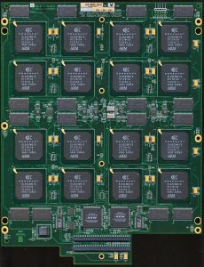
By the late 1990’s as dial in access and ISPs grew to be major concerns dial up solutions became much more sophisticated. Gone were wire racks of modems and in were rackmount all in one dial in solutions. These included boards that hosted dozens of modems on one PCB. with their own processing and management built in. One of the largest companies for these solutions was Ascend Communications. Their ‘MAX TNT’ modem solution once boasted over 2 million dial up ports during the 1990’s. Such was Ascends popularity that they merged with Lucent in 1999, a deal that was the biggest ever at its time, valued at over $24 Billion ($37 Billion in 2020 USD). It wasn’t just traditional ISPs that needed dial up access, ATM’s and Credit Card processing became huge users as well. It wasn’t uncommon to try to run a credit card at a store in the 1990’s and have to wait, because the machine got a busy signal. The pictured Ascend board has 48 modems on a single PCB, and would be in a rack or case with several more boards, supporting 100s of simultaneous connections.
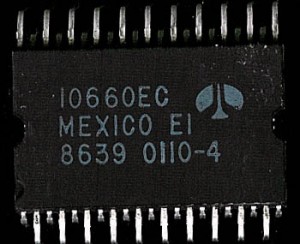
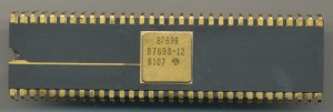
Ascend’s technology was based primarily on modem chips provided by Conexant (Rockwell Semiconductor before 1999). Rockwell had a long history of making modem controllers, dating back to the 1970’s. Most of their modem controllers up through the 80’s and early 90’s were based on a derivative of the 6502 processor. This 8-bit CPU was more the adequate for personal use modems up to 33.6kbaud or so, but began to become inadequate for some of the higher end modems of the 1990’s. These ran at 56k, supported various voice. fax, and data modes and handled a lot of their own DSP needs as well. Rockwell’s solution was to move to an ARM based solution, and integrate everything on chip.
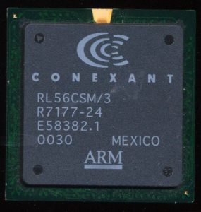
One of the results of this was the Anyport Multiservice Access Processor. It was called the Multiservice Access Process because it handled, voice, data, 33.6/56k, ISDN, cellular, FAX and several other types of data access, and it did so in triplicate. The RL56CSMV/3 supported 3 different ports on one chip. The CSM3 series was the very first ARM cored device Rockwell produced. Rockwell had licensed the ARM810 (not very common), the ARM7TDMI and a ‘future ARM architecture’ (which was the ARM9) back in January of 1997. In less then two
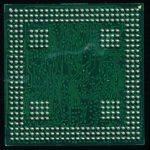
years Rockwell had designed and released the first AnyPort device, remarkable at the time. The CSM/CSMV used the ARM7TDMI running at 40MHz and made on a 0.35u process. The CSM/CSMV has another interesting feature, and thats the backside of the chip….
Take a look of the backside of the 35mm BGA chip, the ball arrangement is very unusual! There is a ring of balls around the outer edge and 4 squares of 16 balls inside of that. This is a multi-die BGA package. There are 4 die inside one BGA package, three dies for the 3 Digital Data Pumps (DDPs) and a seperate die for the ARM7 MCU (which is made on a different process then the mixed signal DDPs). Most of the balls in the 16×16 squares are to be connected to GND, and used for thermal dissipation (dissipating heat via the main PCBs ground plane). Its not uncommon to see multidie packages today, but a multi die BGA package in 1999 was fairly innovative.
 Surprisingly many of these chips are still in service, in today’s world of high speed broadband connections there are still many who are stuck on dial up. As recently as 2015 AOL was still serving 2.1 million dial up customs in the US (out of around 10 million dial up customers total), which was still netting the company nearly half a billion dollars a year (by far their largest source of revenue at the time. There is also still plenty of other infrastructure that still rely on dial up, ISDN, and even FAX services that require end point connections like the CSMV so its end is probably still a long ways off.
Posted in:
CPU of the Day


