Navy Hydrophone Noise Canceller: Weitek 3332 Floating Point Based DSP
I got these boards some time ago, hoping to be able to figure out more about them but alas, information is very sparse, but they are such good looing boards, with impressive technology for the day, I had to post them
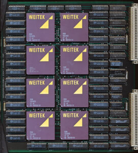
These boards came out of a US Navy system labeled “Hydrophone Noise Canceller” which seemed to be part of SONAR test system at a University. These date from the late 1980’s to the early 1990’s. The system was comprised of 16 boards, 12 8 Channel DSP board, a control board, and 3 Ethernet Boards, Each of these boards is a very heavy 4 layer PCB, with pretty much everything socketed.
The DSP Boards are based on the Weitek 3332 FPU. These are full 32-bit Floating point datapaths (MULT/DIV/ADD/SUB + Registers) and made on a CMOS process. They operate on a 100ns (10MHz) clock. THese are the higher end version of the 3132, they have a full 3 busses versus the single bus of the 3132. These 3 busses add a lot to the pincount (168 vs 144) and thus cost but make designing a system more flexible, no bus sharing to worry about. The 3332 was designed specifically to support high speed DSP and graphics processing. It performed the ‘core’ of a DSP, allowing the user to build around it and make essentially a custom DSP for their application (unlike the purpose built TI TMS320 series of DSPs also available at them time) On the board they are backed by 4 Cypress CY7C128 2K SRAM per processor (8K total). There is no clock crystal on the board itself, which is typical of a system like this. To ensure everything stays in synch, the clock would be provided by the control board and distributed to each of the boards on the bus.
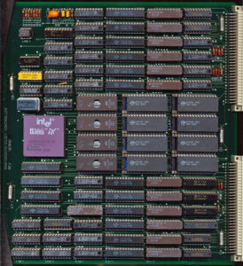
The Control Board runs an Intel A80386DX processor. On this particular board its a 25MHz chip, but note the crystal next to it is an 80MHz crystal. A 386 internally divides the clock by 2, so the 80MHz clock is most like divided by 2 externally resulting in a 40MHz input to the 80386, and a 20MHz CPU clock. I had another controller board with a 20MHz 80386 so they probably just used what ever they had available. This is Serial # 2 afterall. The 386 is supported by 4 27C256 EPROMs and 8 32K (CY7C198) SRAM chips, giving it 256K of SRAM. In addition is 12 8k (CY7C185) 8K SRAM chips each with there own Pipeline Register.
A typical 386 system would have several MB of RAM, but this system is set up for real time data processing, as a DSP system, so the only data that needs to be in RAM is the control program itself, so 256K of system RAM is a great plenty. Additional RAM is likely used solely for buffering data from the Hydrophones.
It would be interesting to know what this board was used for in more detail, but even if that never happens its an interesting board for its time. Clearly a vast amount of effort went into designing and building the system.


