Archive for January, 2020

January 24th, 2020 ~ by admin

ARMing the Modems of the 1990’s

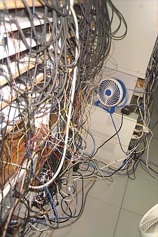
Racks of external modems at an ISP back in the day

Back in the 1990’s I worked at several ISP’s in my hometown.  These were the days of dial up, and by working at the ISP I got free dial up access which my family and I enjoyed.  We had several racks (white wire racks) of external modems for dial in.  This was the most common solution for smaller ISPs.  External modems were usually more reliable, cheap and easy to replace if/when they failed (and they did).  They got warm so it wasn’t uncommon to see a fan running to help move more air.  Surprisingly I could only find a few pictures of a such installations but you get that idea.

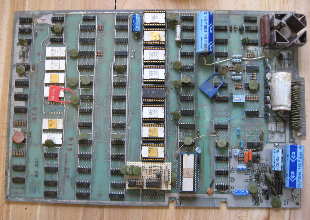
By the late 1990’s as dial in access and ISPs grew to be major concerns dial up solutions became much more sophisticated.  Gone were wire racks of modems and in were rackmount all in one dial in solutions.  These included boards that hosted dozens of modems on one PCB. with their own processing and management built in.  One of the largest companies for these solutions was Ascend Communications.  Their ‘MAX TNT’ modem solution once boasted over 2 million dial up ports during the 1990’s.  Such was Ascends popularity that they merged with Lucent in 1999, a deal that was the biggest ever at its time, valued at over $24 Billion ($37 Billion in 2020 USD). It wasn’t just traditional ISPs that needed dial up access, ATM’s and Credit Card processing became huge users as well.  It wasn’t uncommon to try to run a credit card at a store in the 1990’s and have to wait, because the machine got a busy signal.  The pictured Ascend board has 48 modems on a single PCB, and would be in a rack or case with several more boards, supporting 100s of simultaneous connections.

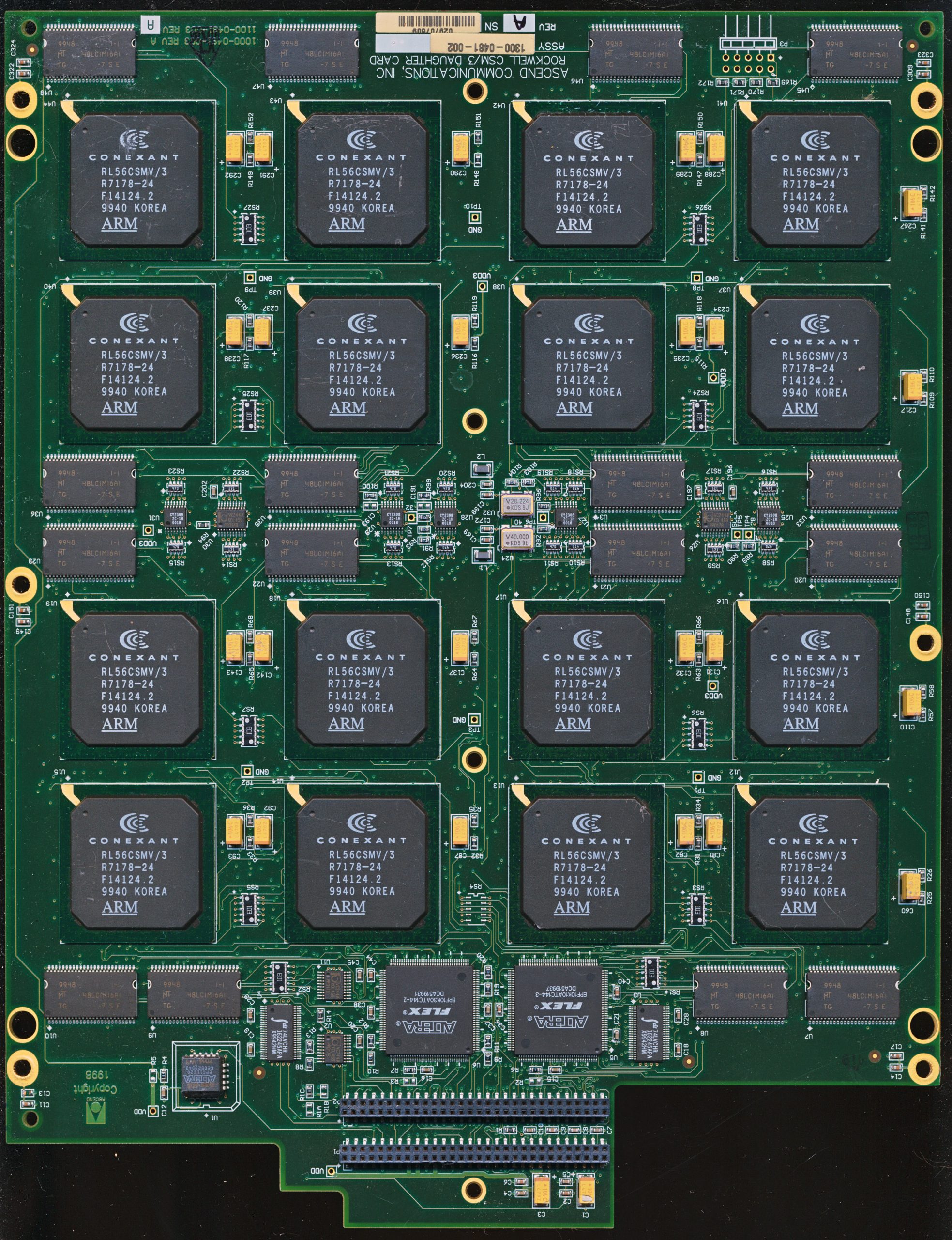
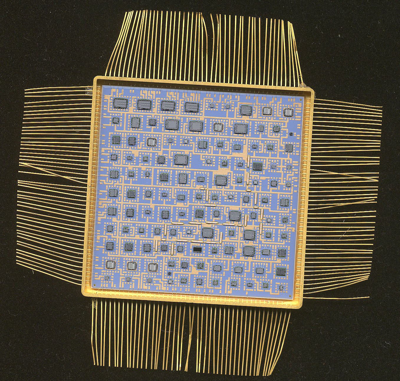
Ascen CSM/3 – 16x Conexant RL56CSMV/3 Chips provide 48 modems on one board.

Ascend’s technology was based primarily on modem chips provided by Conexant (Rockwell Semiconductor before 1999).  Rockwell had a long history of making modem controllers, dating back to the 1970’s.  Most of their modem controllers up through the 80’s and early 90’s were based on a derivative of the 6502  processor.  This 8-bit CPU was more the adequate for personal use modems up to 33.6kbaud or so, but began to become inadequate for some of the higher end modems of the 1990’s.  These ran at 56k, supported various voice. fax, and data modes and handled a lot of their own DSP needs as well.  Rockwell’s solution was to move to an ARM based solution, and integrate everything on chip.

One of the results of this was the Anyport Multiservice Access Processor. It was called the Multiservice Access Process because it handled, voice, data, 33.6/56k, ISDN, cellular, FAX and several other types of data access, and it did so in triplicate.  The RL56CSMV/3 supported 3 different ports on one chip.  The CSM3 series was the very first ARM cored device Rockwell produced.  Rockwell had licensed the ARM810 (not very common), the ARM7TDMI and a ‘future ARM architecture’ (which was the ARM9) back in January of 1997.  In less then two

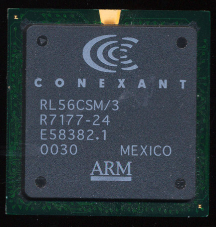
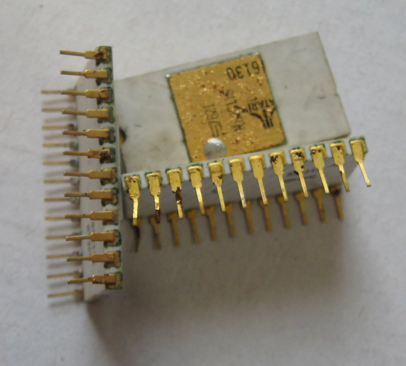
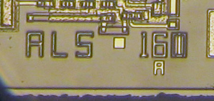
Conexant RL56CSM/3 R7177-24 ARM7 (non-V version has no voice support)

years Rockwell had designed and released the first AnyPort device, remarkable at the time.  The CSM/CSMV used the ARM7TDMI running at 40MHz and made on a 0.35u process.  The CSM/CSMV has another interesting feature, and thats the backside of the chip….

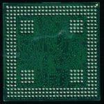
Take a look of the backside of the 35mm BGA chip, the ball arrangement is very unusual!  There is a ring of balls around the outer edge and 4 squares of 16 balls inside of that.  This is a multi-die BGA package.  There are 4 die inside one BGA package, three dies for the 3 Digital Data Pumps (DDPs) and a seperate die for the ARM7 MCU (which is made on a different process then the mixed signal DDPs).  Most of the balls in the 16×16 squares are to be connected to GND, and used for thermal dissipation (dissipating heat via the main PCBs ground plane).  Its not uncommon to see multidie packages today, but a multi die BGA package in 1999 was fairly innovative.

Surprisingly many of these chips are still in service, in today’s world of high speed broadband connections there are still many who are stuck on dial up.  As recently as 2015 AOL was still serving 2.1 million dial up customs in the US (out of around 10 million dial up customers total), which was still netting the company nearly half a billion dollars a year (by far their largest source of revenue at the time.  There is also still plenty of other infrastructure that still rely on dial up, ISDN, and even FAX services that require end point connections like the CSMV so its end is probably still a long ways off.

Tags:
, ,

Posted in:
CPU of the Day

January 14th, 2020 ~ by admin

Barn Find MOS MCS6502 – A Restoration

ATARI Arcade BoardIn car collecting one of the ‘holy grail’ experiences is the ‘Barn Find’  finding and recovering a rare vehicle that has sat untouched, in some barn, or shed for some time.  They are often in rough, but original condition and can evoke much excitement.  As it turns out CPUs are not so different.  I recently purchased a very rough and very old ATARI Arcade board.

The pictures clearly showed it in terrible condition, with lots of oxidation and ‘stuff’ on it.  But it also had a white MOS 6502 processor.  These are some of the very first CPUs made by MOS and are rather desirable, as in addition to their use by ATARI, they were used in the very first Apple computer, the Apple 1.

When the board arrived it was clearly in bad shape, take a look at that nastiness.  What you can’t see, or rather smell, is the cow manure.  Clearly this board was in an actual barn at some point.  Probably relegated to such a retirement after serving in an Arcade parlor or bar for some time, either that or there was some bovin gaming going on.

You can see there is some oxidation on the lids of the various chips as well.  The ROMs and CPU are in sockets.  These sockets are nice, they are not a machine socket but rather a LIF, Low Insertion Force Socket, that helps as the pins on these chips are very delicate, and very possibly corroded.

Before attempting to remove the MCS6502 its best to see what I am working with, so I pulled some of the ROMs nearest to the 6502 to see how their pins looks and how easy they came out of their sockets.  They came out with not a lot of effort but you can see there is some oxidation on the pins.  What we do not want is the pins to be rusted TO the socket and then break off from the forces needed to remove the chip from the socket.

To help mitigate this risk I used some penetrating oil on the pins in the socket.  It seems strange to be squirting oil in the socket but it works.  It will help penetrate the rust and decrease the force needed to remove the 6502. After adding the oil I let the board sit on my heater in my office for several hours.  This helps the oil penetrate, as well as made my office smell like Deep Creep and cow manure, all in a days work.

Then I very gently work on removing the 6502, testing how tight it is and working it out from both ends.  It comes looses with very little drama, hopefully with all its pins intact….

Read More »

Tags:
, ,

Posted in:
How To

January 2nd, 2020 ~ by admin

Chips in Space: Making MILSTAR

Milstar Satellite

Back in the late 1970’s having a survivable space based strategic communications network became a priority for the US Military.  Several ideas were proposed, with many lofty goals for capabilities that at the time were not technologically feasible.  By 1983 the program had been narrowed to a highly survivable network of 10 satellites that could provide LDR (Low Data Rate) strategic communications in a wartime environment.  The program became known as MILSTAR (Military, Strategic, Tactical and Relay) and in 1983 President Reagan declared it a National Priority, meaning it would enjoy a fair amount of freedom in funding, lots and lots of funding.  RCA Astro Electronics was the prime contractor for the Milstar program, but during the development process was sold to GE Aerospace, then Martin Marietta, which became Lockheed Martin before the 3rd satellite was launched.  The first satellite was suppose to be ready for launch in 1987, but changing requirements delayed that by 7 years.

Milstar Program 5400 series TTL dies

The first satellite was delivered in 1993 and launched in February of 1994.  A second was launched in 1995 and these became Milstar-1. A third launch failed, which would have carried a hybrid satellite that added a Medium Data Rate (MDR system).  Three Block II satellites were launched in 2001-2003 which included the MDR system, bringing the constellation up to 5.  This provided 24/7 coverage between the 65 degree N/S latitudes, leaving the poles uncovered.

TI 54ALS161A

The LDR payload was subcontracted to TRW (which became Northrup Grumman) and consisted of 192 channels capable of data rates of a blazing 75 – 2400 baud.  These were designed for sending tasking orders to various strategic Air Force assets, nothing high bandwidth, even so many such orders could take several minutes to send.  Each satellite also had two 60GHz cross links, used to communicate with the other Milstar sats in the constellation.  The LDR (and later MDR) payloads were frequency hopping spread spectrum radio system with jam resistant technology.  The later MDR system was able to detect and effectively null jamming attempts.

The LDR system was built out of 630 LSI circuits, most of which were contained in hybrid multi layer MCM packages.  These LSIs were a mix of custom designs by TRW and off the shelf TTL parts.  Most of the TTL parts were sourced from TI and were ALS family devices (Advanced Low Power Schottky), the fastest/lowest power available.  TI began supplying such TTL (as bare dies for integration into MCMs) in the mid-1980’s.  These dies had to be of the highest quality, and traceable to the exact slice of the

Traceability Markings

exact wafer they came from. They were supplied in trays, marked with the date, diffusion run (a serial number for the process and wafer that made them) and the slice of that wafer, then stamped with the name/ID of the TI quality control person who verified them.

These TTL circuits are relatively simple the ones pictures are:
54ALS574A Octal D Edge Triggered Flip flop (used as a buffer usually)
54ALS193 Synchronous 4-Bit Up/Down Binary Counters With Dual Clock
54ALS161A Asynchronous 4-Bit Binary Counters

ALS160-161

Looking at the dies of these small TTL circuits is quite interesting.  The 54ALS161A marking on the die appears to be on top of the a ‘160A marking.  TI didn’t make a mistake here, its just that the the 160 and 161 are essentially the same device.  The 161 is a binary counter, while the 160 was configured as a decade counter.  This only required one mask layer change to make it either one.

ALS573 and ALS574 die

Similarly with the 54ALS574, which shares a die with the more basic ‘573 D type transparent Latch.  This was pretty common with TTL (if you look at a list of the different 7400 series TTL you will notice many are very similar with but a minor change between two chips).  It is of course the same with CPUs, with one die being able to be used for multiple core counts, PCI0E lanes, cache sizes etc.

Together with others they perform all the function of a high reliability communications systems, so failure was not an option.  TI supplied thousands upon thousands of dies for characterization and testing.  The satellites were designed for a 10 year lifetime (it was hoped by them

Milstar Hybrid MCM Command Decoder (picture courtesy of The Smithsonian)

something better would be ready, no doubt creating another nice contract, but alas, as many things are, a follow on didn’t come along until just recently (the AEHF satellites).  This left the Milstar constellation to perform a critical role well past its design life, which it did and continues to do.  Even the original Milstar 1 satellite, launched in 1994 with 54ALS series TTL from the 1980s is still working, 25 years later, a testament to TRW and RCA Astro’s design.  Perhaps the only thing that will limit them will be the available fuel for their on-orbit Attitude Control Systems.

While not necessarily a CPU in itself these little dies worked together to get the job down.  I never could find any of the actual design, but it wouldn’t surprise me if the satellites ran AMD 2901 based systems, common at the time or a custom design based on ‘181 series 4-bit ALUs.  finding bare dies is always interesting, to be able to see into whats inside a computer chip, but to find ones that were made for a very specific purpose is even more interesting.  The Milstar Program cost around $22 Billion over its life time, so one must wonder how much each of these dies cost TRW, or the US Taxpayer?

Tags:
, ,

Posted in:
CPU of the Day