
Aeroflex UT80CRH196KDS – The MCS-196 Goes to Space
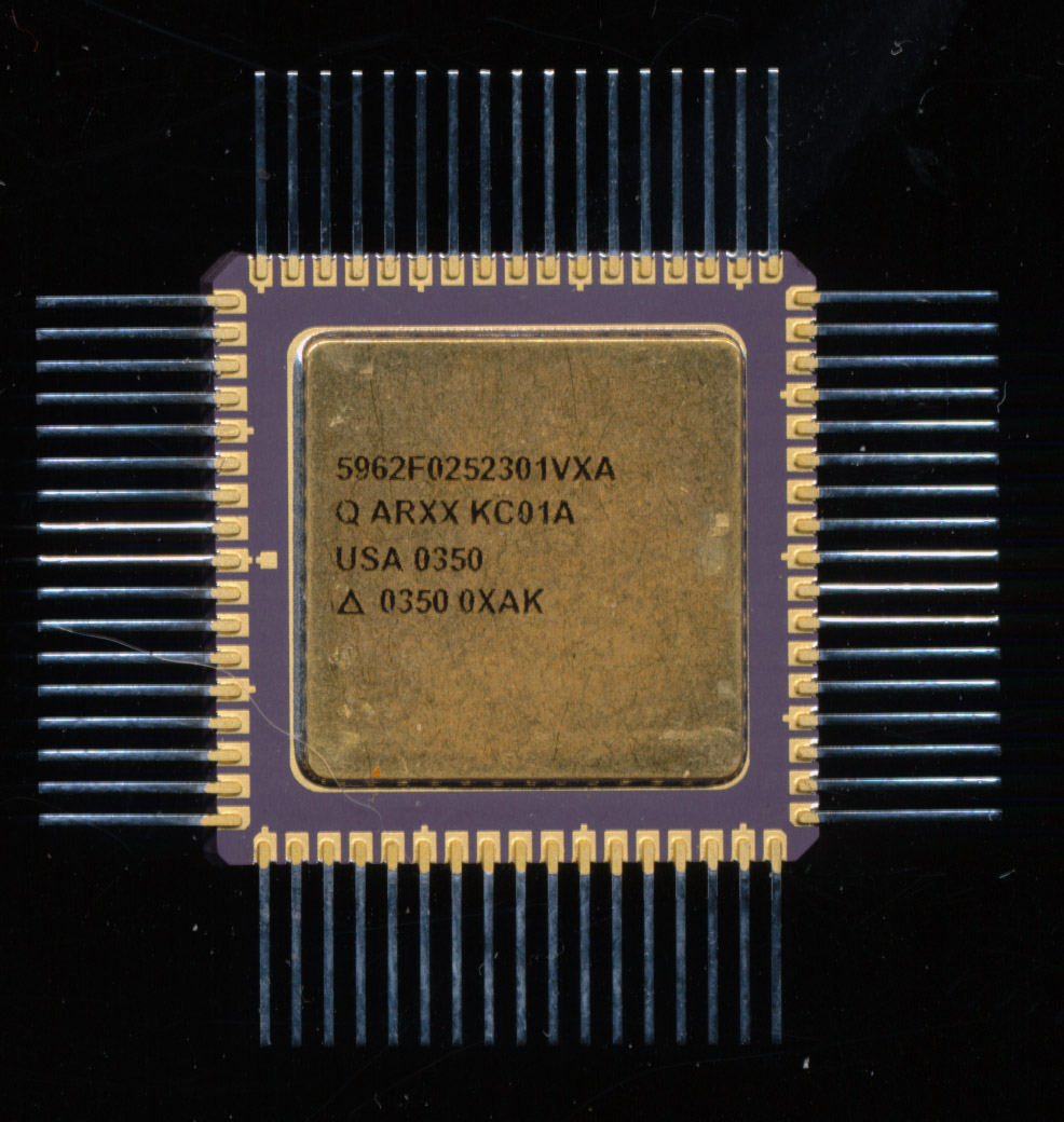
Aeroflex 5962F0252301VXA = UT80CRH196KDS
F = 3×10⁵ Rad
01 = Mil Temp (-55C-125C)
V = Class V
The MCS-196 is the second generation of Intel’s MCS-96 family of 16-bit processors. These are a control oriented processor originally developed between Ford Electronics, and Intel in 1980 as the 8060/8061 and used for over a decade in Ford engine computers. They include such things as timers, ADC’s, high-speed I/O and PWM outputs. This makes them well suited for forming the basis of applications requiring control of mechanical components (such as Motors, servos, etc). The 196KD is a 20MHz CMOS device with 1000 bytes of on die scratch pad SRAM. The UT80CRH196KDS (unqualified/not tested for radiation) is priced at $1895.00 in quantities of 5,000-10,000 pieces (in 2002). Fully qualified ones will of course cost a lot more. The KDS is a drop in replacement for the previous KD version, which only supported doses of 100krads.
This obviously lends itself to automotive applications, hard disk control, printers, and industrial applications. There is however, another application they have found wide spread use in, spacecraft. Spacecraft are not all to different from a car in the amount of mechanical systems that must be interfaced to the computer controls. The difference however, is that unlike your car, spacecraft electronics must work, always. If a car fails, its an annoyance, if a spacecraft fails, it has the potential to cost millions of dollars, not to mention the loss of a mission. If that spacecraft happens to be the launch vehicle, a failure can directly result in a loss of life.
That is why processors such as the UT80CRH196 are made. Aeroflex UTMC (now a division of Cobham) is a Qualified Manufacturer for military spec devices. The 196 pictured is the highest spec available at the time. There are 2 key specifications for this device. The ‘F’ in the part number refers tot the radiation hardness level of the device. This particular device is rated at total radiation dose 3×10⁵ Rads (300,000). This is the maximum dose it would see in Low Earth Orbit, and close to the peak dose seen in a Geostationary or deep space application (shielding is used in those applications to reduce the total dose the electronics package is exposed to, sch as used on the Juno probe currently in orbit around Jupiter). 400 rads is typically enough to cause radiation sickness, 1Krad is survivable by most commercial microchips, and doses of 10Krads will kill you.
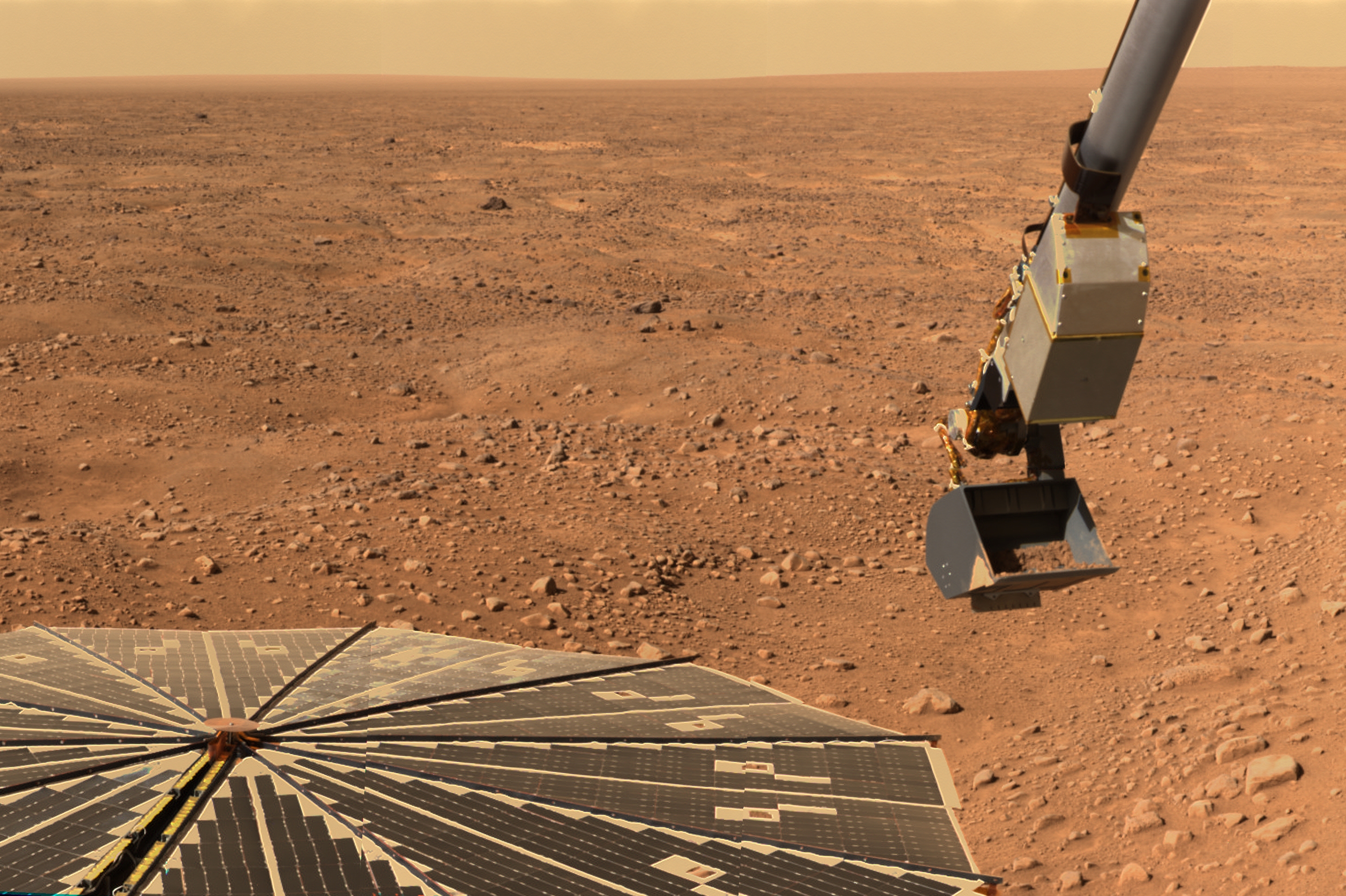
Mars Phoenix Lander – Launched in 2008 Used a 80CRH196KD for its Mass Spectrometer
Testing of the radiation hardness is done using several methods. Radiation effects electronics in several ways, predominately in slowly breaking down the device, as well as single event effects, where a ‘burst’ of radiation causes the device to latch up (requiring a reset of the system). Total ionizing dose is usually tested by exposing the device to a sample of Cobalt-60. The device is then electrically tested, with the results needing to match the pre-dosing values, or be within a certain allowable range of those values. This ‘196 sees the idle current increased from 55mA to 62mA after a 300 Krad dose a result of damage from the radiation causing increased leakage current. Idle current raises from 6mA to 19mA, a rather large increase, but a known increase that can be designed for. Total ionizing dose is what physically breaks down the IC itself. Given enough exposure, over time, the device WILL fail, the goal is to keep those failures within a known range.
Latch-up testing is tested with either of two radiation sources: 1) a flash x-ray machine (FXR), or 2) an electron linear accelerator (LINAC). These are used to see if the device can continue to function without latching up due to a burst of radiation. And if it does latch up, how fast does it recover. These are done at relatively high energies, in the order of 2-10 MeV.
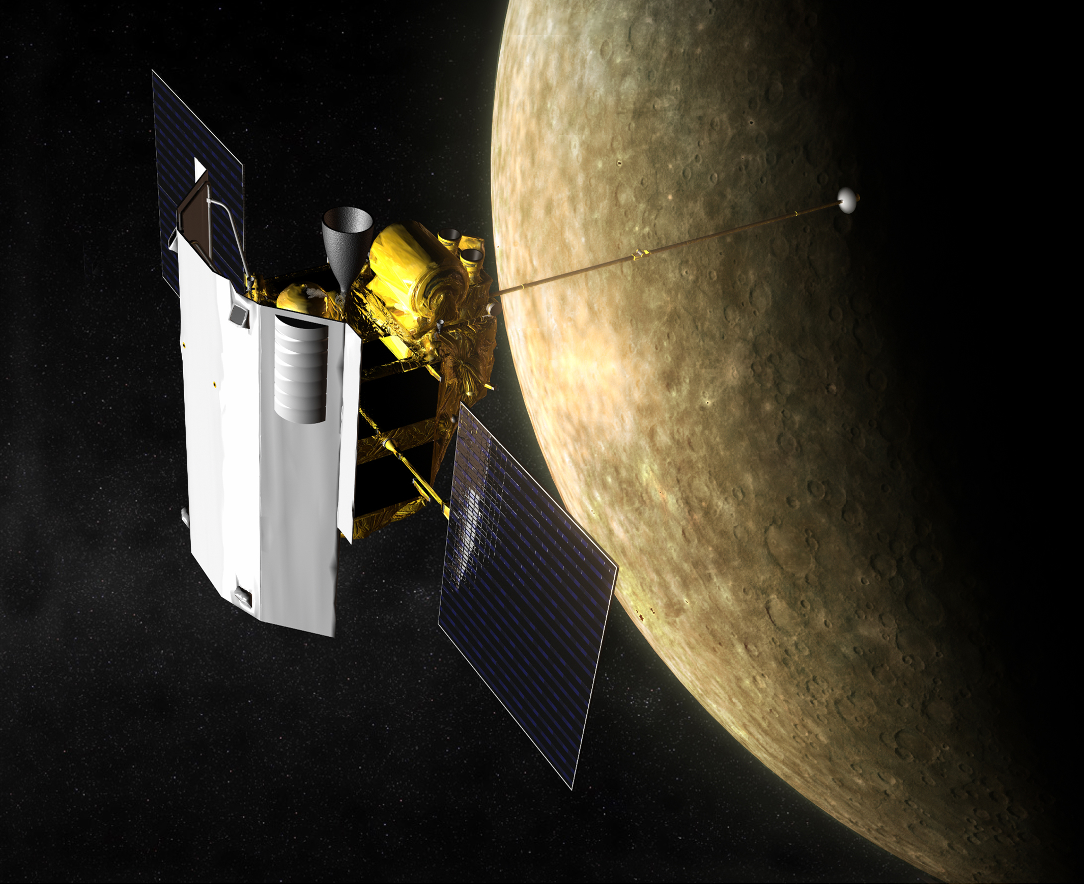
The 2004-2015 MESSENGER mission to Mercury used a 80CRH196KD for its Laser Altimeter System (MLA)
MIL-STD-883 is the standard used for testing, documentation and suitability of electronics for use by the military and other institutions. It specifies what levels of qualification a device must meet for a variety of different end uses. There are some applications where a device failure is not ideal, but is acceptable. A military RADAR, for example, should work, but if it fails, it can and will be repaired. This is the most common class of screening known as Class B. Each Class requires acceptance of the previous Class’s requirements in addition to more testing, and/or more stringent acceptance testing. A lower class may find a failure of 1 part in 50 to be acceptable, while a more stringent class may not.
This UT80CRH196KDS is screened to a Class V standard. Class V is the most stringent screening available in the MIL-STD-883. It is what is required for Launch vehicles, satellites, and missiles. It is the minimum standard specified by NASA for many missions. Validation of a manufacturing line for production of integrated circuits for use in space systems (Class V) shall be accomplished by a team headed by DSCC with observers solicited from NASA, Air Force Space and Missiles Center, the services, and the customer. As important as the testing is, even more important is the documentation. Every device has to be able to be tracked back to its wafer or wafer, and documentation of the testing of that wafer, and device follows that device wherever it ends up. In testing there is an allowable number of devices that do not pass the test, for Class V, for all tests, that allowable number is 0. If a single device fails, the entire lot is rejected, and documentation is made as to why the device failed. Each device must have a 240-hour burn-in, and be inspected via X-ray. Packaging is also tested to endure the package the die goes in will not fail itself (stress fractures in the ceramic, bond wire/lead failures etc.
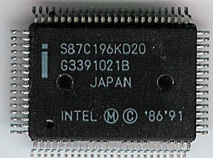
Intel S87C196KD20 – From which the Aeroflex part is based.
This ensures that these devices are of the highest quality, reliability, and acceptable for use in space, particularly in vehicles/applications that are carrying humans. This does not mean that the device will not fail, just that it is the most likely not to. When a failure does occur, its source may be more easily determined due to the documentation and traceability of these parts. Failure is particularly unacceptable if nothing is learned from it.
The Aeroflex ‘196 has been widely used in space, and likely will continue to be. The 2008 Mars Phoenix lander used the it to control its mass spectrometer and the MESSENGER Mercury mission in 2004-2015 used it to control the Laser Altimeter. It also runs the attitude control system of the NPSAT1, to be launched later this year on a SpaceX Falcon Heavy.
There are of course, other ways of designing reliability into systems. Both the Space Shuttle, and the SpaceX Falcon 9/Dragon use multiple flight computers that continually check each others results, if one computer encounters an error, it is taken off line. This is a form of radiation tolerance, rather than strict hardening (though both may be used at once). The system can tolerate the effects of radiation (limited to single event effects) and continue the mission. This is acceptable though only for use cases that are 1) very short such as a rocket that is only being ‘used’ for a few minutes, or 2) applications where the hardware can be fixed or exchanged such as on the ISS or the Space Shuttle. Cases where the hardware is inaccessible, such as satellites or space probes, mandate the use of radiation hardened devices. We still as of yet, have no way to swap out the electronics package on a rover on Mars (though soon perhaps we will) so it must be designed to survive in a high radiation environment.