
Barn Find MOS MCS6502 – A Restoration
 In car collecting one of the ‘holy grail’ experiences is the ‘Barn Find’ finding and recovering a rare vehicle that has sat untouched, in some barn, or shed for some time. They are often in rough, but original condition and can evoke much excitement. As it turns out CPUs are not so different. I recently purchased a very rough and very old ATARI Arcade board.
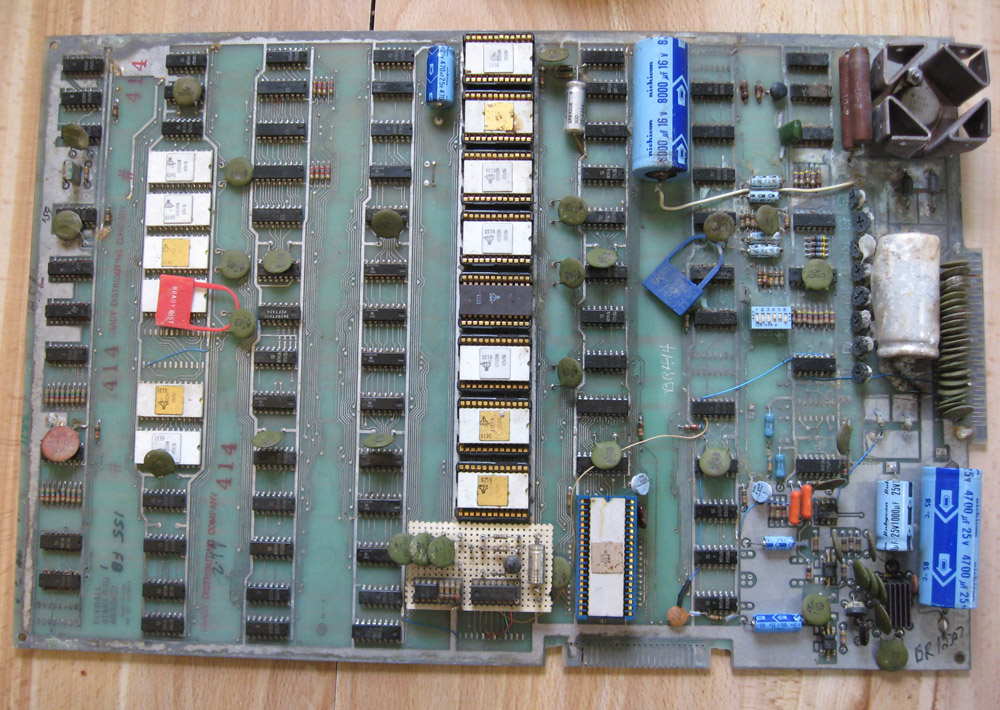
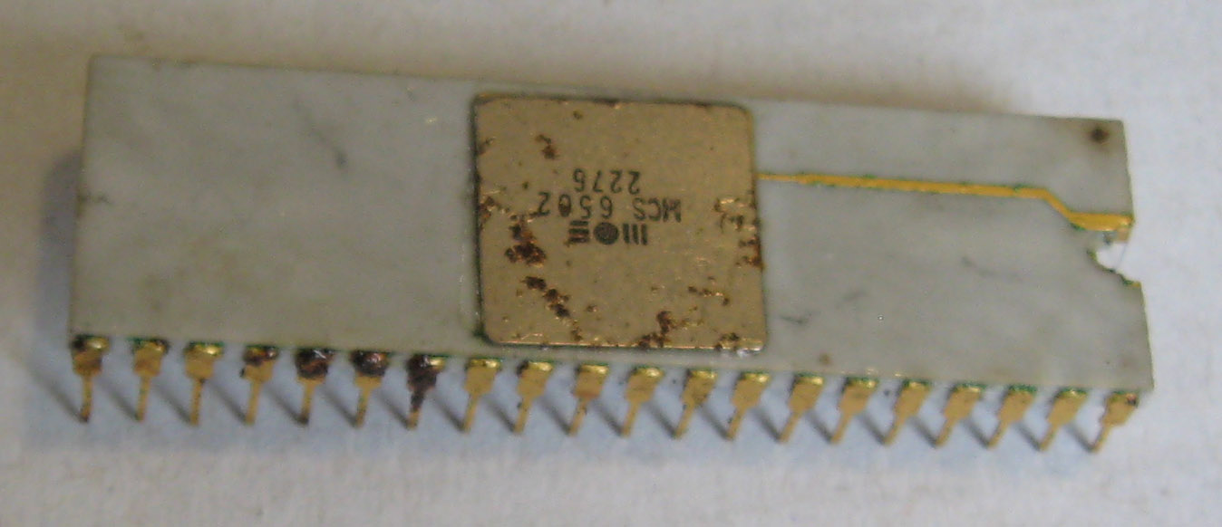
The pictures clearly showed it in terrible condition, with lots of oxidation and ‘stuff’ on it. But it also had a white MOS 6502 processor. These are some of the very first CPUs made by MOS and are rather desirable, as in addition to their use by ATARI, they were used in the very first Apple computer, the Apple 1.
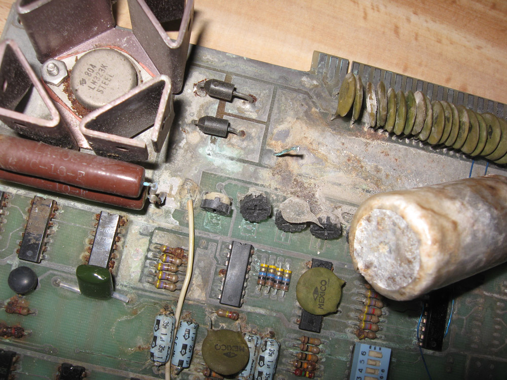
When the board arrived it was clearly in bad shape, take a look at that nastiness. What you can’t see, or rather smell, is the cow manure. Clearly this board was in an actual barn at some point. Probably relegated to such a retirement after serving in an Arcade parlor or bar for some time, either that or there was some bovin gaming going on.
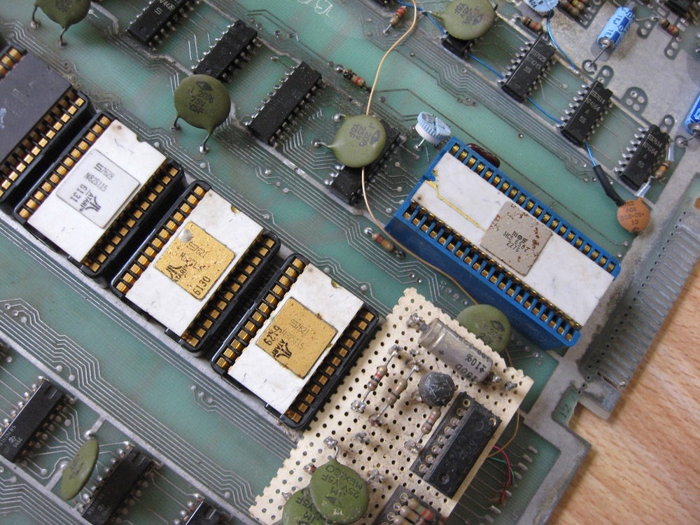
You can see there is some oxidation on the lids of the various chips as well. The ROMs and CPU are in sockets. These sockets are nice, they are not a machine socket but rather a LIF, Low Insertion Force Socket, that helps as the pins on these chips are very delicate, and very possibly corroded.
Before attempting to remove the MCS6502 its best to see what I am working with, so I pulled some of the ROMs nearest to the 6502 to see how their pins looks and how easy they came out of their sockets. They came out with not a lot of effort but you can see there is some oxidation on the pins. What we do not want is the pins to be rusted TO the socket and then break off from the forces needed to remove the chip from the socket.
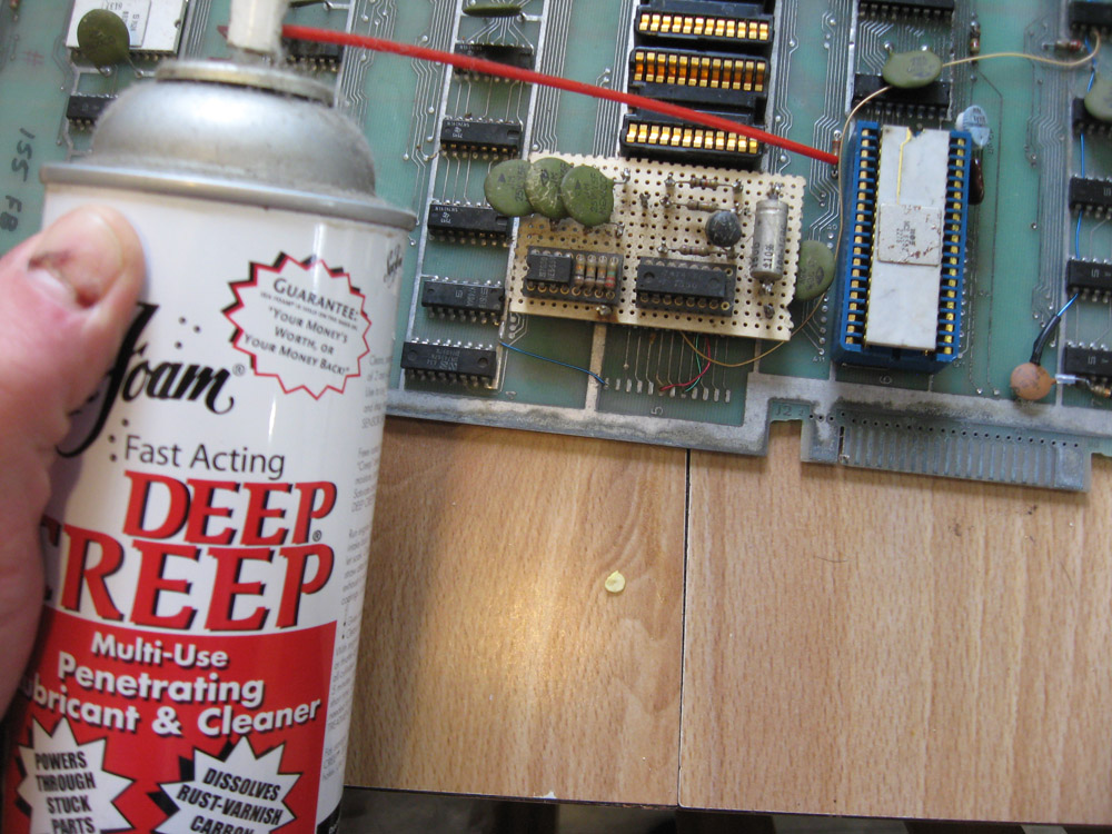
To help mitigate this risk I used some penetrating oil on the pins in the socket. It seems strange to be squirting oil in the socket but it works. It will help penetrate the rust and decrease the force needed to remove the 6502. After adding the oil I let the board sit on my heater in my office for several hours. This helps the oil penetrate, as well as made my office smell like Deep Creep and cow manure, all in a days work.
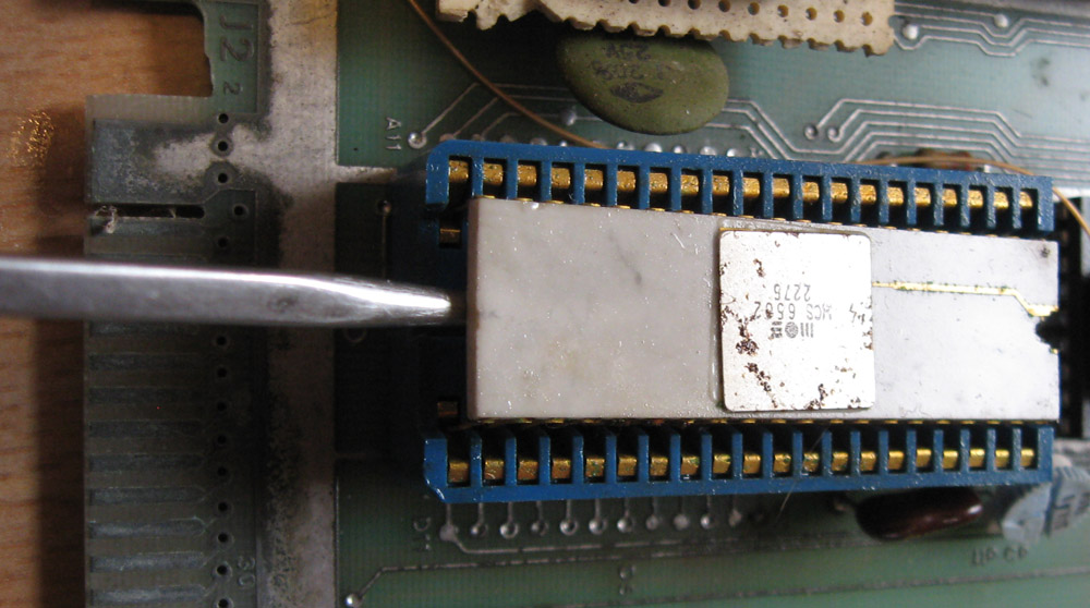
Then I very gently work on removing the 6502, testing how tight it is and working it out from both ends. It comes looses with very little drama, hopefully with all its pins intact….
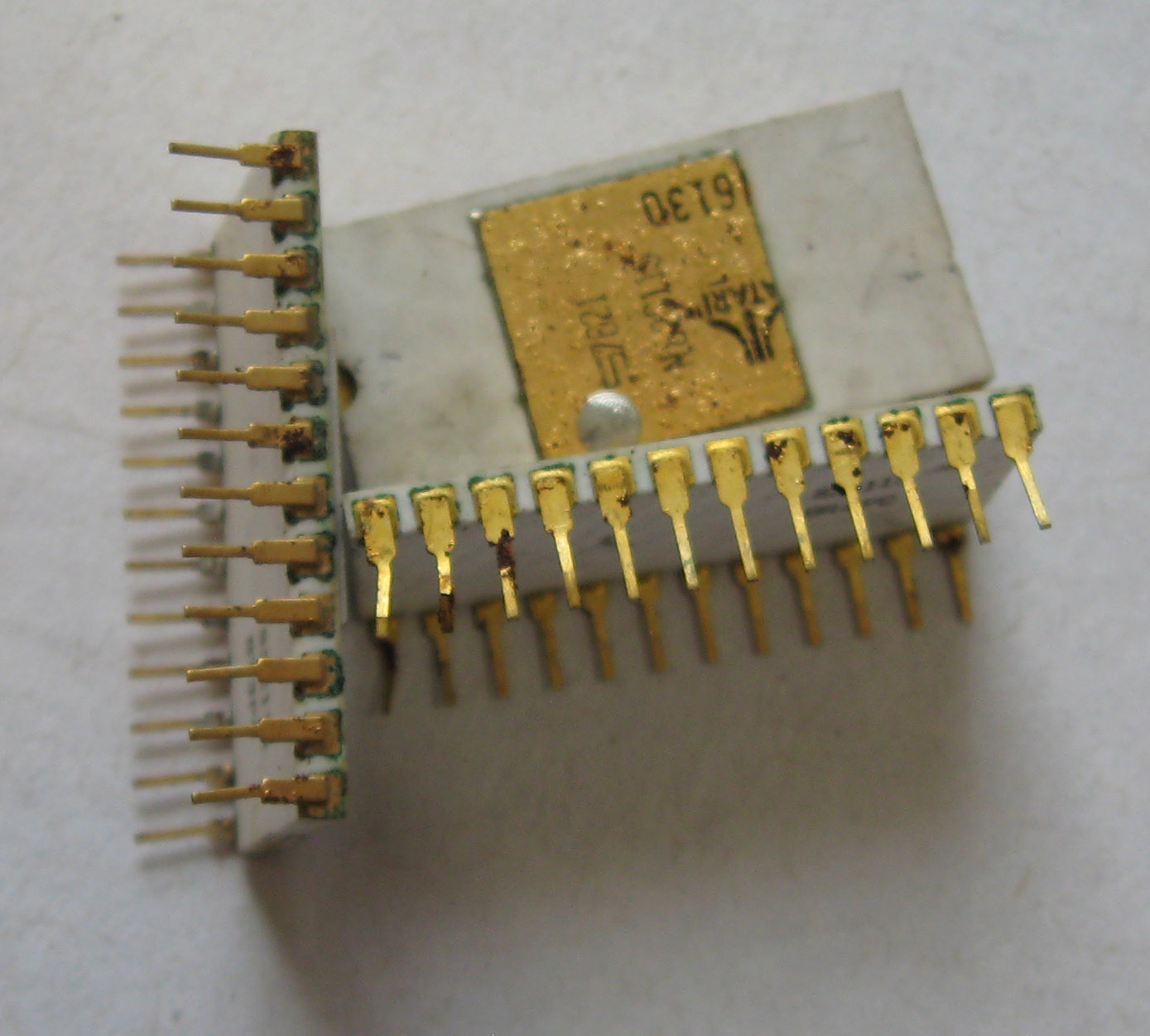
Indeed! All the pins are there. The oil definitely helped as you can see 3-4 pins have some pretty good rust on them. That is from moisture getting under the gold plating and bubbling up. The pins at least seemed solid but now its time for some cleaning.
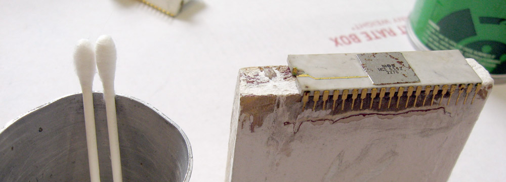
I have a wooden block I specifically made for these more delicate operations. The chip can sit on the wood supporting the chip and the back of the pins, allowing them to be cleaning without being bent.
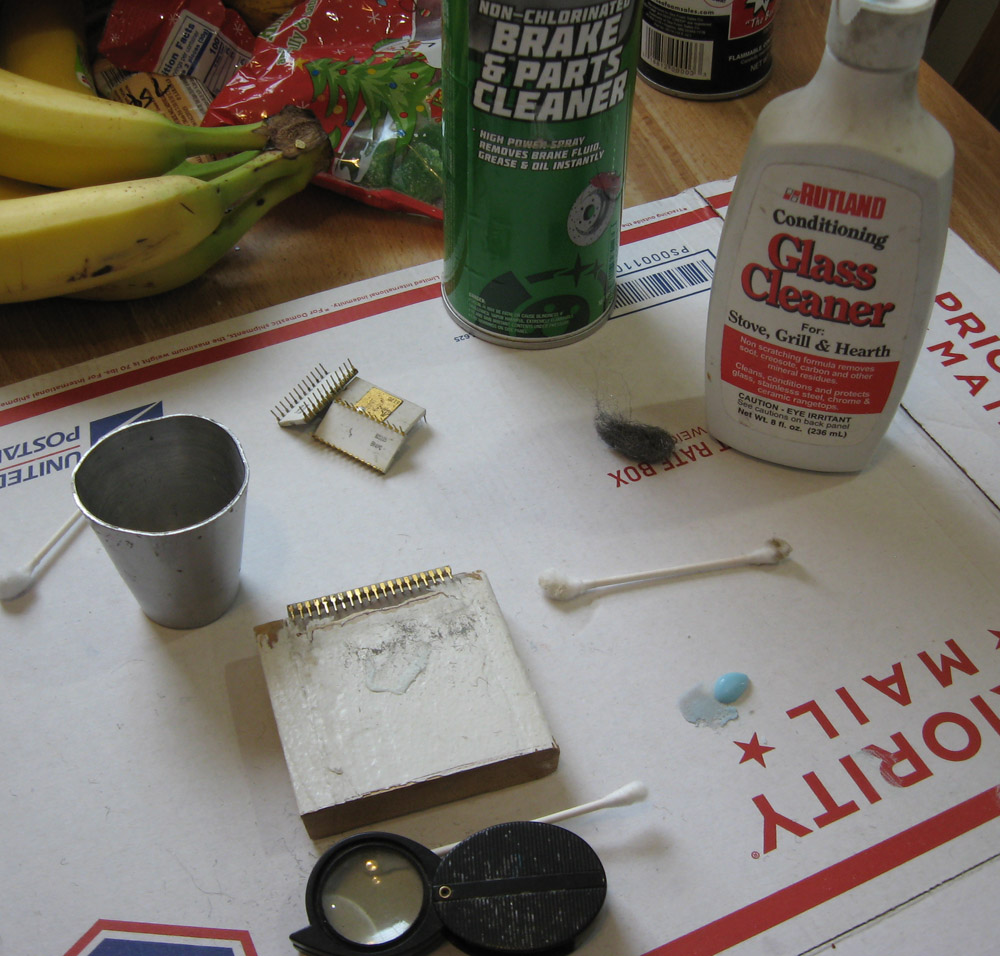
Various tools are used in this operation.
- Cotton Swabs – for applying various cleaners and getting dirt off
- Brake Cleaner – this is an Acetone based cleaner with Xylene, works very well for getting dirt off as well as removing the oils
- Glass Cleaner – This is a very mild polishing compound, excellent for cleaning the pins of minor oxidation and cleaning the ceramic
- Steel Wool – Use very very careful in long wiping motions, its easy to catch a pin wrong, but its needed to get some of the heavier rust off
- Container – Hilariously this is the top of an old Lava Lamp, I use it to hold brake cleaner in for dipping the cotton swabs in
- Magnifying glass – So I can see exactly how the rust looks, how deep, etc
- Banana – For scale
This cleaning process takes me about an hour for this chip, it feel longer and can be nerve wracking, but slow and steady wins the race
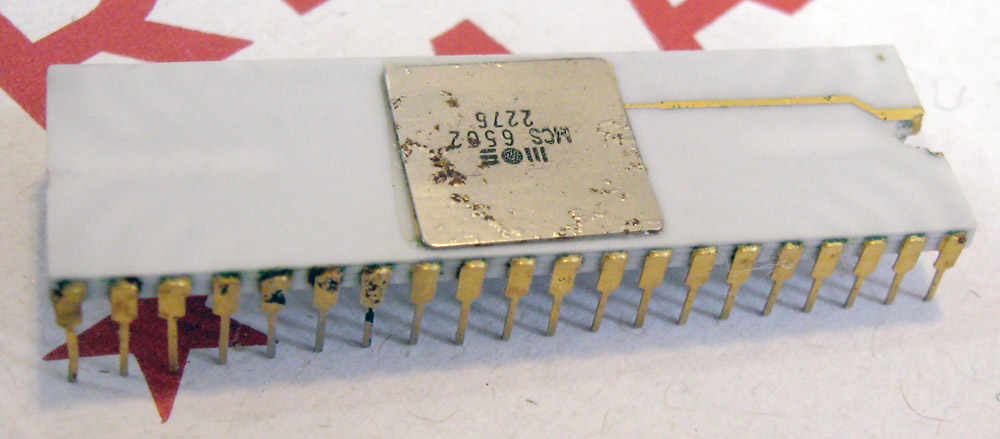
After cleaning here is the MCS6502. The pins still show a little oxidation but the worst is gone. The ceramic is very clean and even the lid is nicer, with less red rust. The lid is best to mostly leave alone, as the markings on these are very delicate, I was surprised they were intact at all. The biggest question though remains. Does this MOS MCS6502 dated May of 1976 still work? Its nearly 44 years old and who knows how long its been since 5 Volts has been applied to its NMOS transistors.
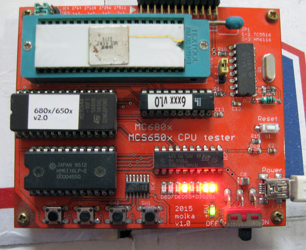
I stick it in the venerable 680x/650x Test Board, ensuring the board is configured right before applying power, and then…flip the switch…and the sight everyone wants to see Blinking LEDs! It passes a function check with flying colors, and when further tested reveals that it is indeed old enough to have the (in)famous ROR bug. The first MCS6502 did not support the ROR (Rotate Right) instruction. It was in fact present, but behaved incorrectly. Michael Steil over at pagetable.com has an excellent article on how the ROR instruction was broken. MOS had chips with working ROR available in June of 1976. That’s RIGHT after this particular 6502 was made, making it one of the very last ROR bug 6502s made.
Its fun to save and restore an old CPU, let alone one with so much history. Not all such finds end up with such a happy ending. Many old chips were set in black foam, that eventually rots the pins right off, always a pity, but today, we had success.
January 29th, 2020 at 12:24 am
Good job with the restore. I am amazed that such old technology can survive for so long and needs a cleanup to work again.
January 30th, 2020 at 10:24 am
Great work! I’m curious to know what kind of success rate you’re seeing on this type of chip restoration? Any thought re: ramping up supply voltage/voltages over time?
February 9th, 2020 at 8:15 am
Great salvage job!
You might try Eagle One Never Dull polishing wadding instead of steel wool for corrosion removal on pins and such. It’s easier to work with and can be wound onto a dremel bit, unlike steel wool.
February 9th, 2020 at 10:54 am
I’ll get some and try it out, thanks for the tip!
February 9th, 2020 at 3:28 pm
The MOS HARDWARE MANUAL, JANUARY 1976, section 1.4.1.2.1 Vcc, Vss–Supply Lines says “The supply voltage on pin 8 is +5.0 V DC ± 5%. The absolute limit on the Vcc input is +7.0 V DC.” – so I don’t think ramping up the voltage over time is within spec. Section 3.4.2 System Power–Step 1 says “It is generally recommended that first prototypes of microcomputer systems be built using sockets for the ICs (processor, memories, etc.). One distinct advantage of this technique is that it allows the designer to verify that Vdd and Vss are properly connected to each socket before the chips are inserted. The Vdd line should be within the tolerances specified about the 5 volt nominal relative to Vss.”
February 9th, 2020 at 9:07 pm
Nice job.
Next time consider testing the adherence of the ZIF socket to the individual pins. After all of the steps you lined out, use something to bend the ZIF socket contacts and observe if it gives freely or seems to stick to the pin. If it sticks, keep doing what you were doing to release it.
Also, this goes to show the longevity of hardware that was built before someone stepped on a soap box about the “evils” of lead in electronics. (I reflect on this every time I successfully boot up hardware that’s more than 40 years old.)
February 10th, 2020 at 12:03 am
Oh man don’t get me started on the problems ‘Lead Free’ created and the amount of electronics polluting landfills because of it
March 4th, 2020 at 8:34 am
What about the ROMs? What game is it?
March 4th, 2020 at 9:09 am
ROMs unfortunately were in very bad shape.
Would have been a nice FlyBall game