
Part 3: Mini-Mainframe at Home: The ALR 6×6 Hardware and BIOS
Par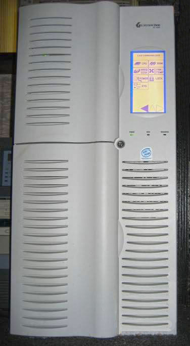 t 3 of The Story of a 6 CPU Server from 1997 – In this section we’ll learn about the hardware and BIOS that makes the ALR Revolution 6×6 with 6 Pentium Pro Processors work.
For the background of the ALR 6×6 and Pentium Pro processors that form the basis of this project please see:
Part 1: Mini-Mainframe at Home – Introduction
Part 2: Mini-Mainframe at Home: Installing a Modern OS
Exterior and Interior
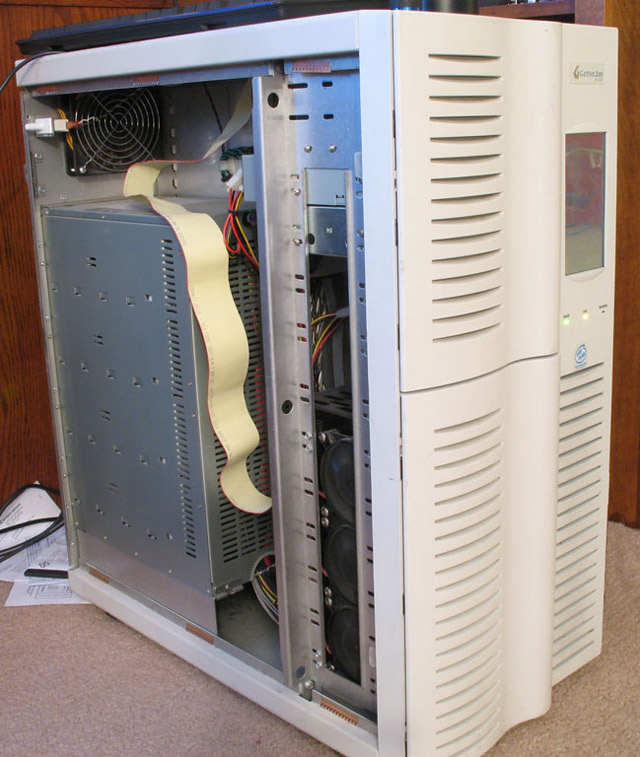
The size of the case is quite large for the desktop (and it came with wheels, so probably not good to have rolling about ones desk), but relatively compact for servers of this class. The height of the server is – 68 cm, width – 32 cm and depth – 58 cm. The weight of the server starts from 52 kg. I have a complete server kit, but the case is missing, because, due to its size and weight, the shipping to Belarus would be around $ 400, if not more, so the photos of the appearance were taken from the Internet.
Editor’s Note: The empty case is currently serving as a kitchen counter at the CPU Shack Museum. Its really THAT big 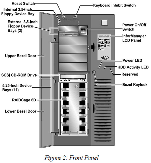
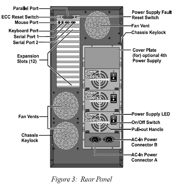
The first thing that catches the eye is the information touch! LCD display, the task of which is to display all the information about the status of the six processors, RAM, temperature, status of hard drives and other vital information. Today, such informative displays are the norm, but 21 years ago I even could not imagine that such a thing ever happened. The front of the case also has two compartments, the upper one under 5.25” devices, such as CD-ROM’s, the lower one opened access to the cage with SCSI drives. Behind you can see 14 expansion slots, a cooling system and a cage with power supplies.
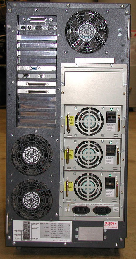
To ensure the operation of the server, two power supplies are needed, which are connected to a special board in the cage. The third power supply unit is a spare one in case of a single power supply failure. It is allowed to install four power supplies with the connection of two pairs to a pair of electrical outlets for complete duplication of all functions providing the server power.
The internal server space is divided into two sections along the entire body. In the left section is the cage with power supplies, the size of a small desktop case. The dimensions of one cage are: height – 39 cm, width – 15.2 cm and depth – 19 cm. The weight of the cage with three power supplies is just over 18kg (40lbs). That’s about the max normal shipping weight, so the PSYs in their cage were the first shipment of this Revolution to Belarus.
In the opposite section is a giant motherboard, the same size as a small office PC.
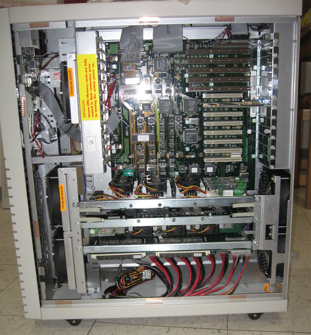
The most interesting is the power supply system of the motherboard, which is built according to the AT scheme, this is evident from the dual power connector (rightmost), as well as six thick black-red power wires from the power supply cage, supplying voltage along the +5 V line. That, using +5 V for the main load on the entire server system is on the line, and nowadays the main loads are usually handled by the 12 Volt bus.
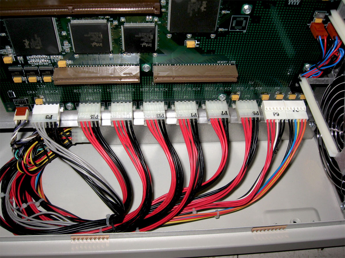
If you add the nameplate power of the six top-end Pentium Pro 200 MHz with 1 MB of L2 cache memory i, you get 282 watts. The maximum power reserve of this server is 700 watts. So, since I have a cage with three power supplies at my disposal, we will consider one of them in more detail.
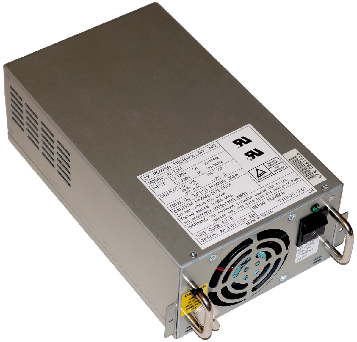
The power supply is equipped with two handles for easy removal from the basket when hot-swappable. There is a toggle switch and LED operation indicator. The power supply is attached with two screws to the basket for secure fixation.
Behind the power supply is as follows:
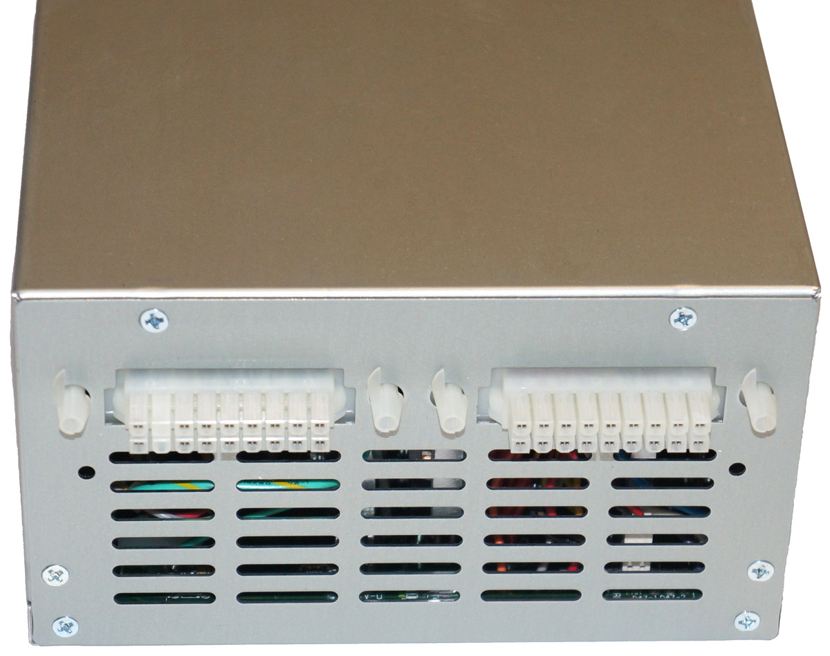
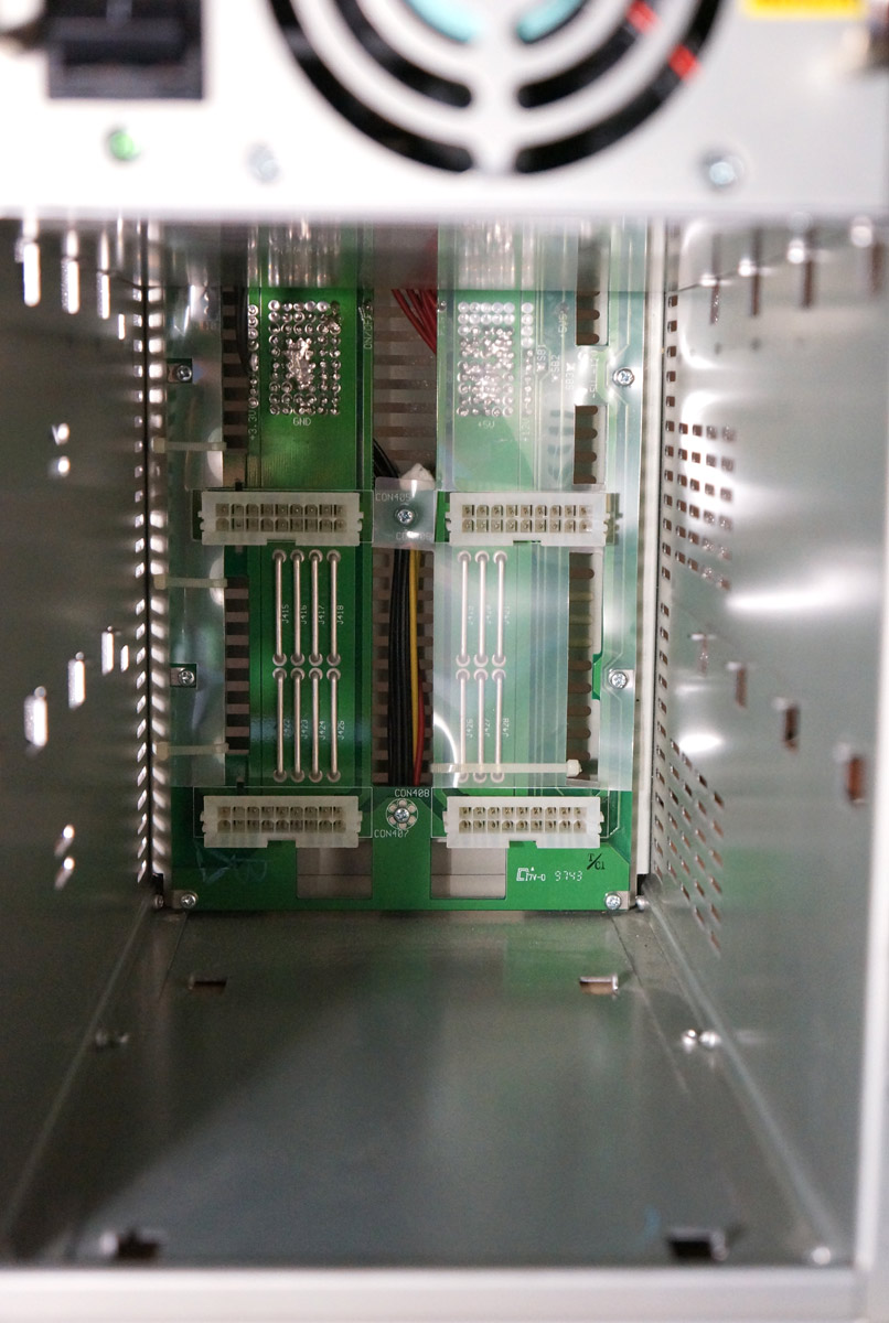
These two non-standard connectors are installed in the cage of the type “father-mother”, ready to hold four such blocks. From the inside the basket looks like this:
The marking of the power supply says that it was manufactured by 3Y Power Technology, which was acquired in 2006 by the well-known manufacturer of power supplies FSP Group. Production date October 1998
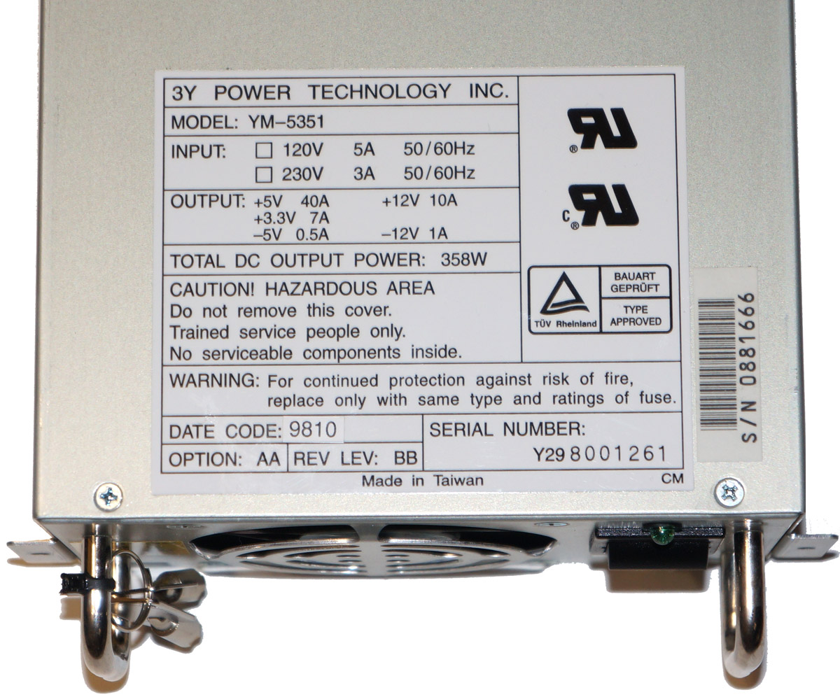
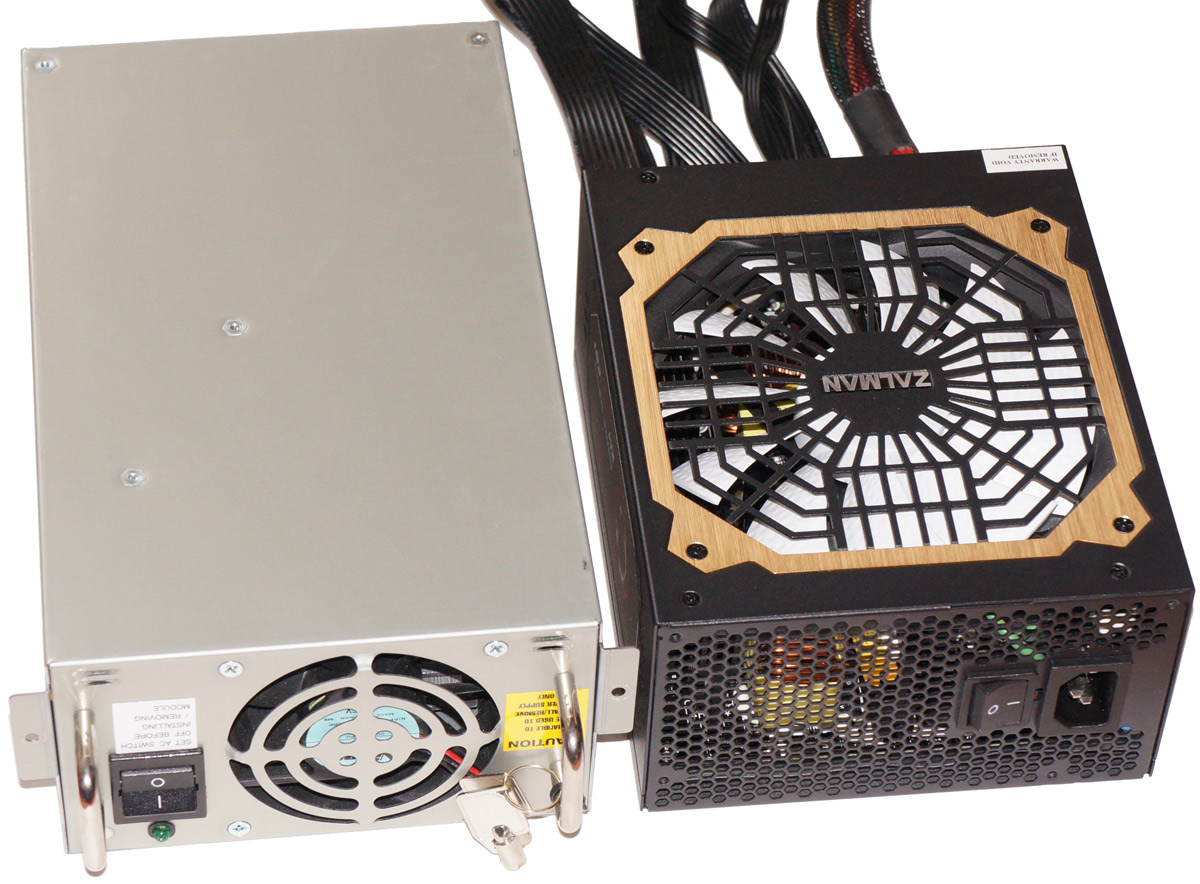
The power supply is capable of delivering 40 amps on the +5 V line, 7 amps on the 3.3 V line and 10 amperes on the + 12 V line. The total power is 358 watts. In order to present and correlate the size of this power supply unit, I positioned it next to the modern 1000 watt power supply, manufactured by Zalman model ZM1000-EBT. Feel what you call a difference.
And if we compare it with power supply units of the early 2000s, then 650 watt Enermax is located nearby, capable of delivering 46 amps via the +5 V line. The size differs almost twice.
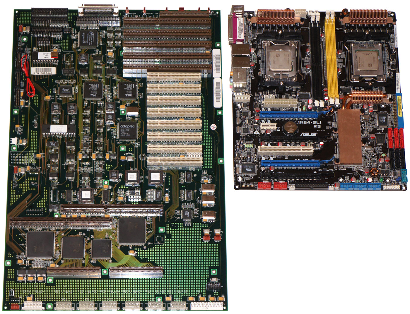
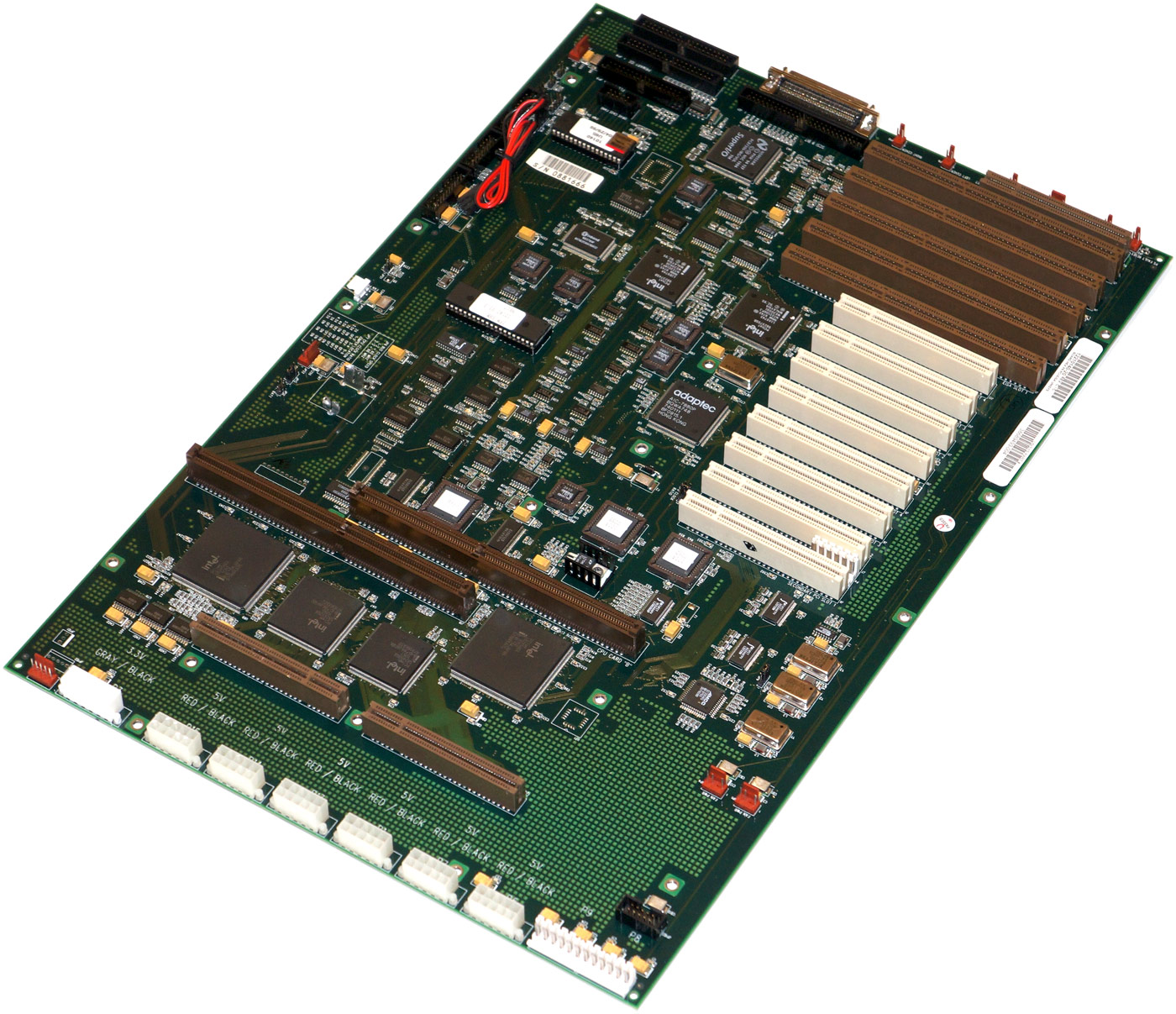 It’s time to go to the main element – the motherboard. To say that she is large, it is not quite enough, she is simply awesome and does not want to fit completely into the lens.
This is simply the largest motherboard I’ve ever held in my hands. Its dimensions are inspirational: width – 33 cm, length – 50 cm. Four large square microcircuits at the bottom of the motherboard are immediately apparent – this is the Intel 450GX chipset. Yes, there was a time when the word chipset meant more than one chip as it is now. The trace routing/signalling design on this board had to be an absolutely nightmare to get right. So many signals, all with timing specs that had to be just right or the whole system would not function. This being further complicated by the fact that the CPUs, and RAM were on external cards.
On either side of the chipset are brown expansion slots. In the lower slot was installed expansion card for RAM. In a pair of top – expansion cards for processors. Each processor board contained three Socket 8 connectors. The boards were mirrored in relation to each other and could be installed in any slot.
Click to enlarge
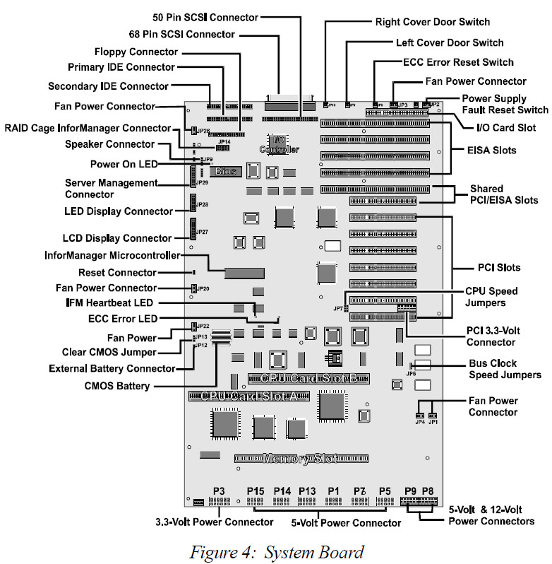
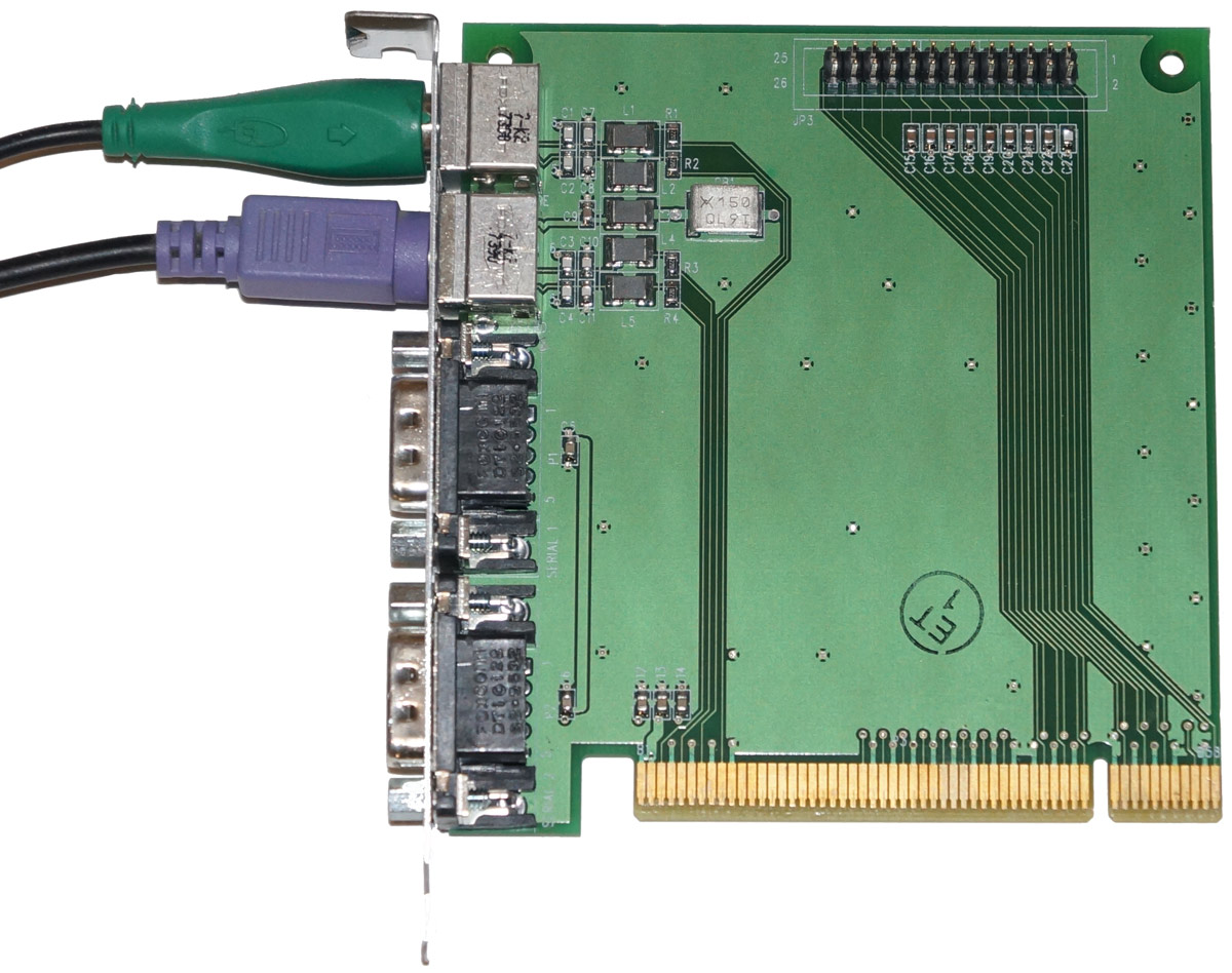
In the middle of the board, there are 8 PCI slots that are connected to two buses. Below are EISA slots. Although they look impressive, in terms of speed, this bus loses the PCI bus, due to its low frequency of operation – 8.33 MHz. A special expansion card with PS/2 connectors for keyboard and mouse and a pair of COM ports is installed in the uppermost connector. Therefore, you will not see any familiar external connectors here, unless looking at the SCSI connector for connecting hard drives.
 |
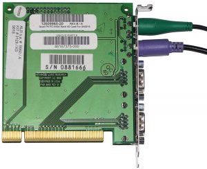 |
If you look at this PS/2 motherboard, you will notice that it was produced by the ALR itself. There are two stickers on the board containing the account numbers of this part according to the ALR and Unisys accounting system, that is, they are interchangeable, like the rest of the server.
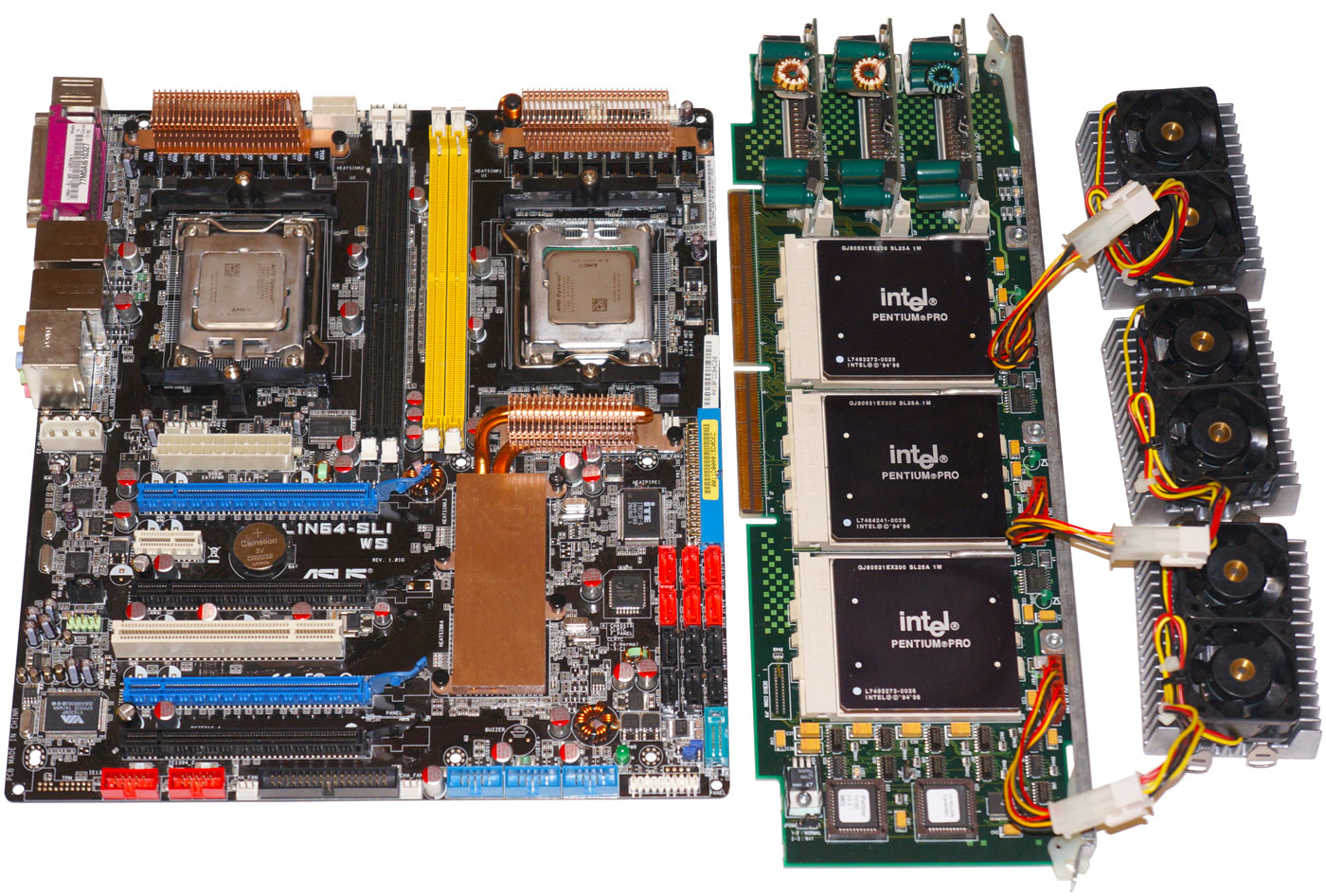
Apart from the Adaptec 7800 SCSI controller, the board has an IDE controller with two IDE connectors and a FDD controller with one connector. For comparison, I put beside the motherboard ASUS L1N64-SLI WS, which, as you remember, is the basis of the AMD platform – “Quadfather” or “Quad FX”.
Impressive, isn’t it? The board is equipped with several diagnostic LEDs, but the most interesting one, in my opinion, is “Heartbeat”. This LED is responsible for the life of the entire system, if it blinks green, then the 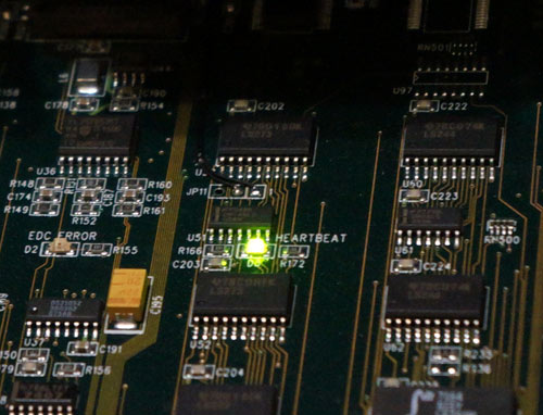 heart of the system beats and everything is in order, similar LEDs are on the processor expansion cards.
If you look at the motherboard more closely, you can simply see the board and special connectors for installing daughter expansion cards. Here you will not see any sockets, connectors for RAM, no power part, all this is on special expansion cards, so if you manage to find a bare board, or the expansion cards themselves, then separately they do not represent any value or interest. But as I had the most complete set of expansion cards from the ALR Revolution 6×6, then I will tell you about all of them in more detail. Let’s start with the processor boards.
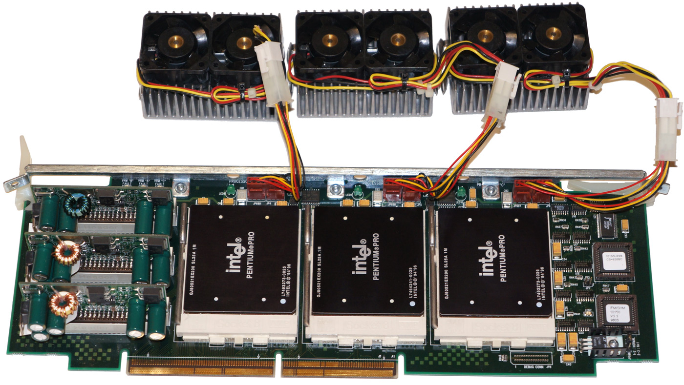
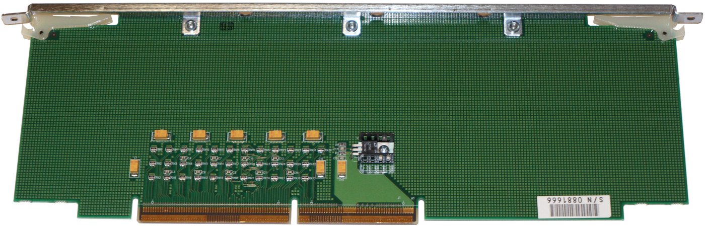
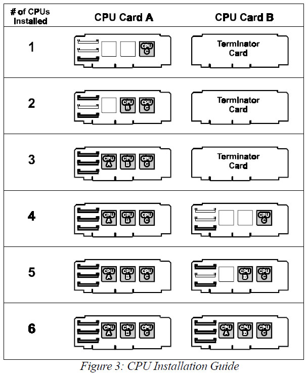
This is one of the processor expansion cards. Installation of two such boards with a total number of processors equal to six is allowed in the motherboard. It is also possible the work of one, two, three, and so on processors. On each of the two such blocks are removable VRM modules, which are installed in proportion to the installed processors. For work processors with less than four pieces, you need to use a terminator board, which is installed in the second slot and looks like this:
The general scheme for connecting processors is presented below in the diagram:
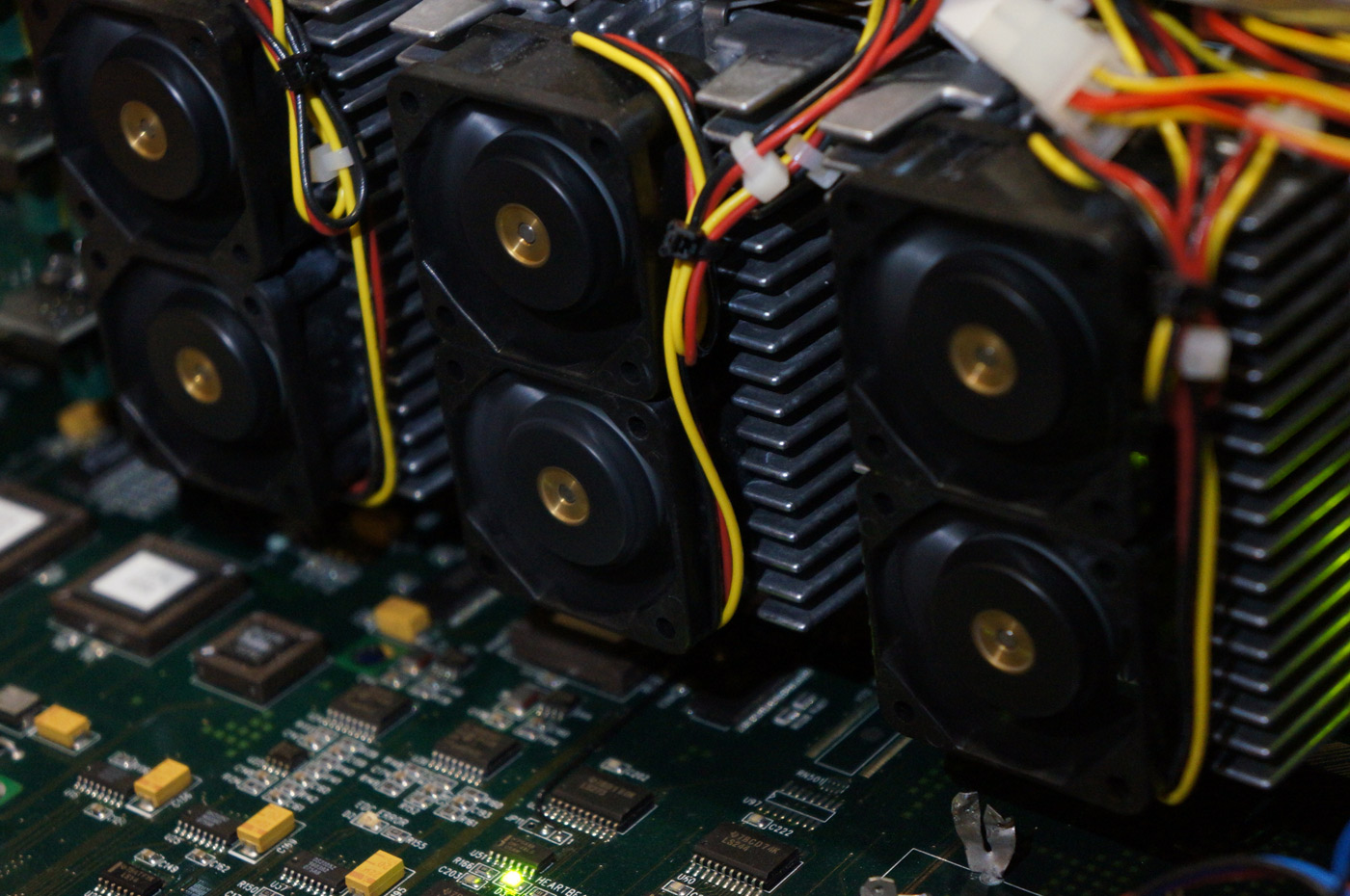
The cooling system for the processors is handled by massive coolers made, by the way, in the USA, each of which is equipped with two high-speed fans. Since the task of such a cooler to remove 47 watts of heat 24 hours a day, the noise emitted by 12 such fans is clearly incomparable and looks like the work of jet engines of an airplane taking off.
This server allows the use of FPM (Fast Page Mode) standard memory in the 72 pin SIMM form factor, as well as in a more modern 168 pin DIMM. Other types of memory, such as EDO, are not supported at the chipset level. In the photo below you can see 128 MB memory in both versions:
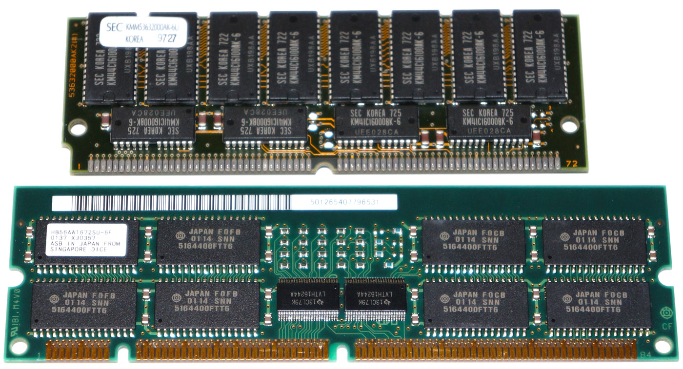
The maximum module size can be 256 MB, which in total with 16 connectors will give a volume of four gigabytes!, Not bad for 1997. Both types of memory were installed in special riser cards.
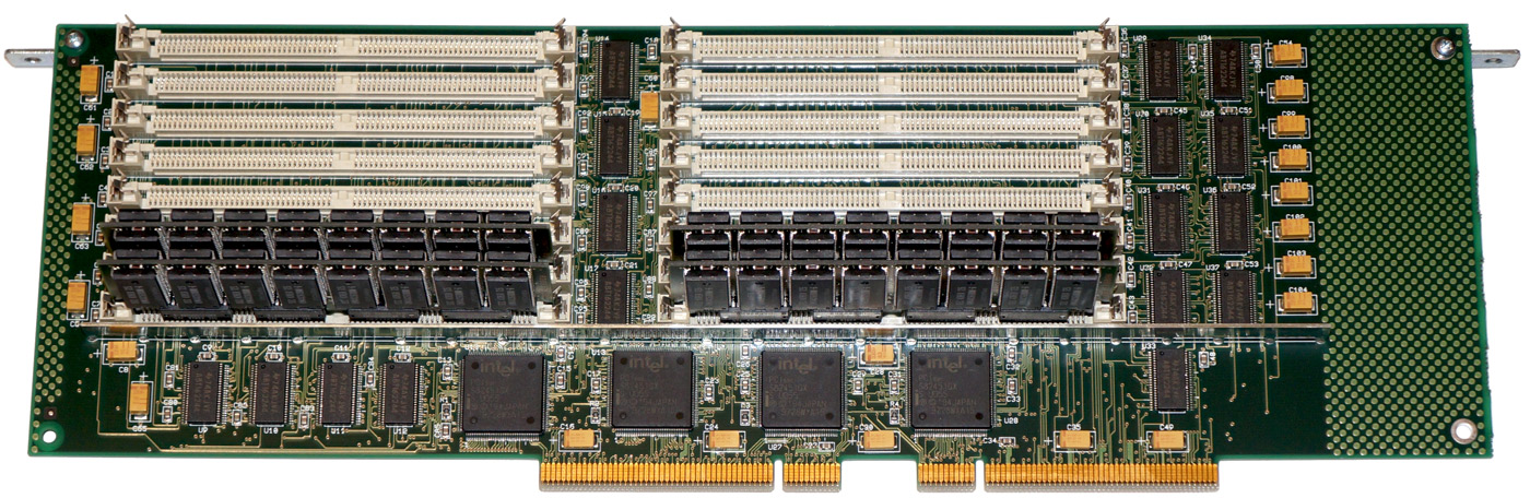
| Below is a photo of a riser card for installing a standard 72 pin SIMM memory with an installed memory of 512 MB.
|
Below is an example of the fact that there is not much memory. Before you, an expansion card for 168 pin DIMMs and 16 memory modules with a total capacity of 2 Gigabytes. For modern purposes, such a volume of RAM is unsuitable, but then it was just huge numbers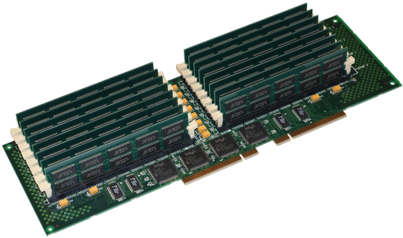 |
For a more high-speed memory mode, it had to be installed according to the following scheme:
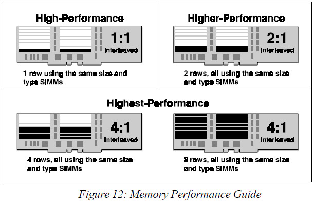 |
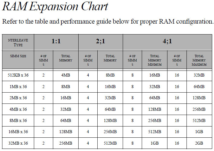 |
This is how all 4 boards look like together:
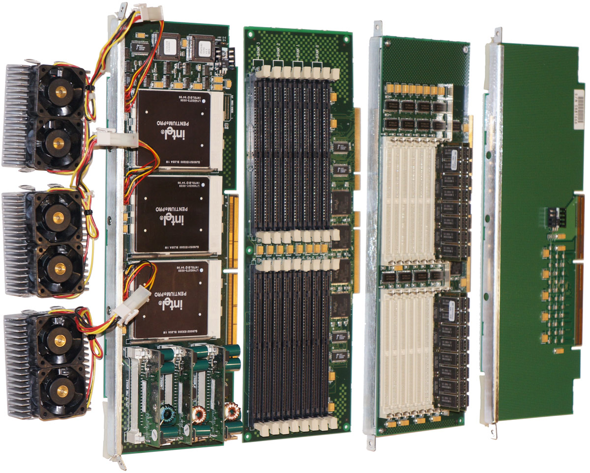
The photo lacks perhaps the second processor riser card. But as a rule, you will not meet all such cards as part of a ready server; we will assume that I got the “Premium” version from ALR, but there is an opportunity for everyone to take a look at such components. How many I did not look for in the “retro” network I could not find reviews of such systems, except for fragmentary messages on the forums, so I decided to write right behind everyone.
And finally, to make it clear what size these riser boards are, I will bring a photo of one of them next to the ASUS L1N64-SLI WS motherboard.
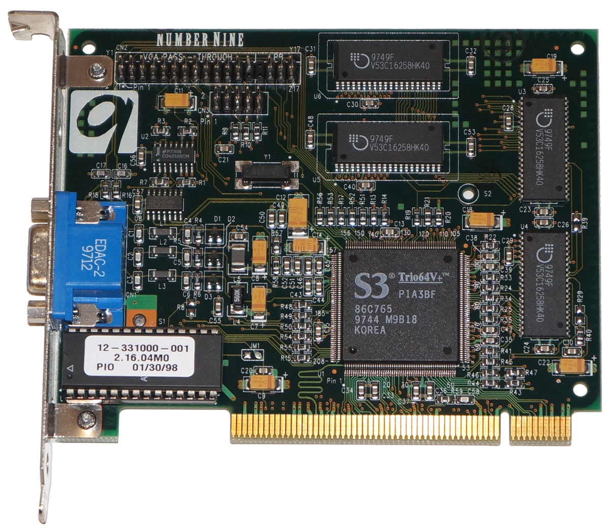
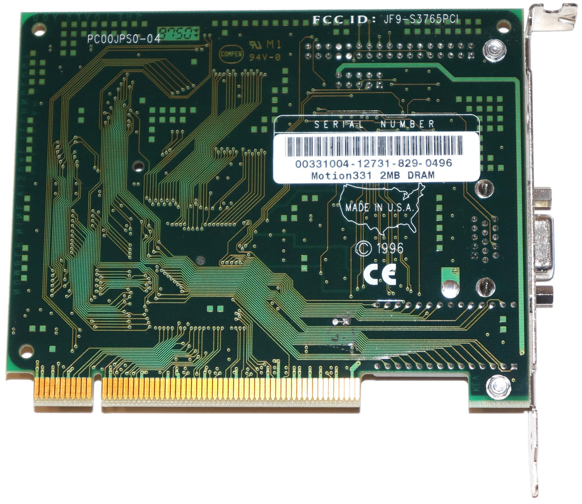
The server package also includes a graphics card with the S3 Trio64V+ GPU made by the famous Number Nine, made in the USA. The amount of video memory which is as much as 2MB, todays video cards memory is measured in GB.
 |
 |
BIOS Setup
After pressing the “Power” button, my six-processor monster comes to life and you can see the long-awaited POST screen on the monitor screen.
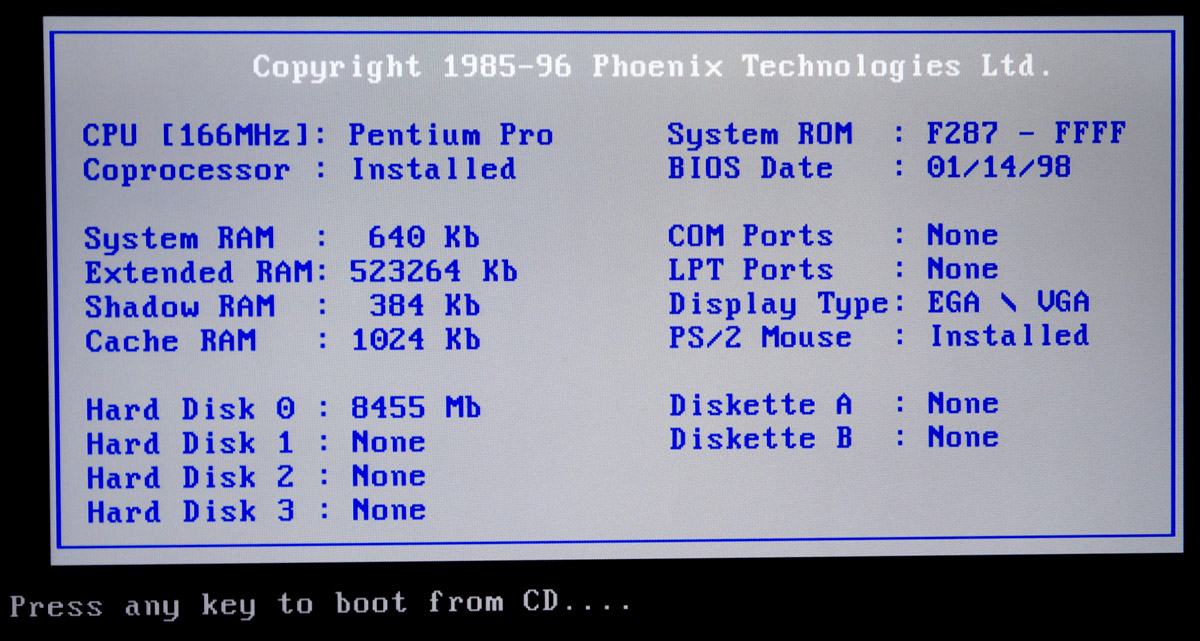
Here is the initial screen of the original ALR Revolution 6×6: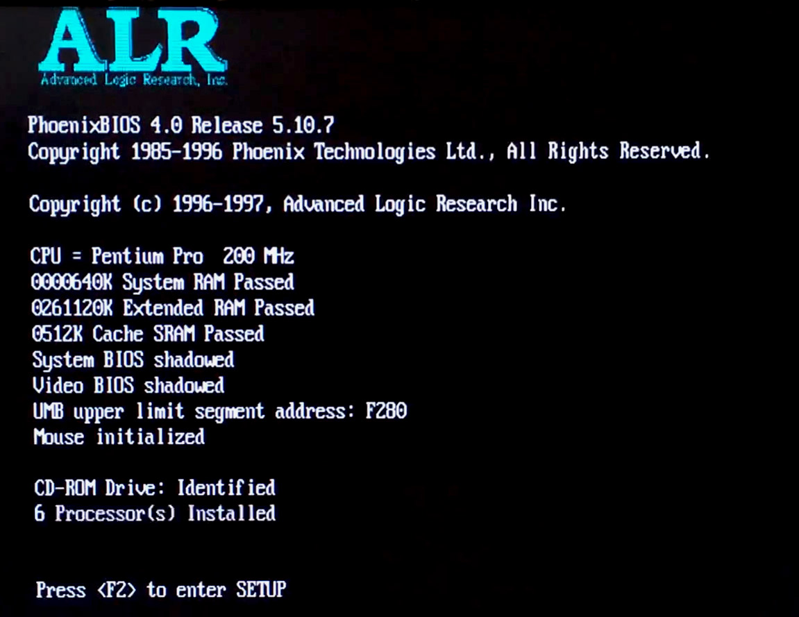 |
And this is what the POST screen of the original Unisys Aquans HS6 looks like:
|
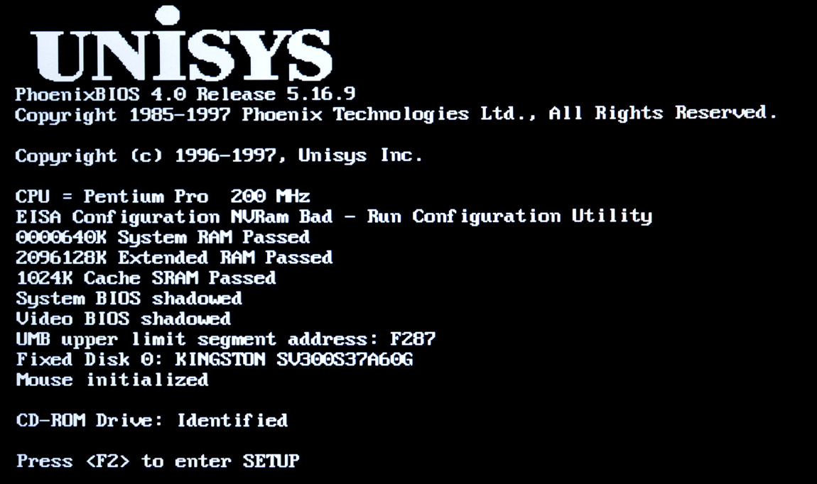
As you can see, this configuration contains 2 GB of RAM and SSD SSDNow V300 with a capacity of 60 GB from Kingston, as well as IDE DVD-RW from Pioneer DVR-109BK, all the components feel great together. Just press “F2” and we will go to Paradise, more precisely the BIOS LOL. But we will not go there immediately. Who saw how ancient PCs recalculate Megabytes for megabytes all available RAM, then remember that this process is not fast. And when on board as much as 2 Gigabytes, then you can make a cup of coffee during the wait. The fact is that scanning the entire available volume takes a little more than 4 minutes of time, for 4 Gigabytes it will take nine to ten minutes. Pressing the Esc key or any other key does not interrupt the process at all, so you have to be patient.
If you count the number of “resets” made by me during the testing process, then the time spent will be about 1/2 a day.
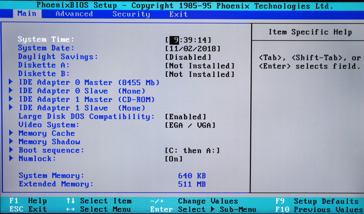
Above the photo shows the initial BIOS Setup screen. I’ll say right away that there are no various options here, everything is done in a minimalist style, since the main principle of the server is uninterrupted work 24/7, 365 days a year. The photo shows that the volume of a 60 GB SSD disk connected via an IDS-SATA adapter is 8.5 GB – this is the standard limitation of the BIOS of those years, but the OS means that the entire volume becomes available to us without any problems inherent in such restrictions.
You may also notice that booting is possible either from disk “A” – floppy drive, or from disk “C” – hard disk. It is not possible to choose booting from a CD-ROM in BIOS and at first I even thought that I would have to get the floppy disk again, but the boot disk in the drive was determined in the BIOS and the system offered to start booting from it, it was a pleasant surprise.
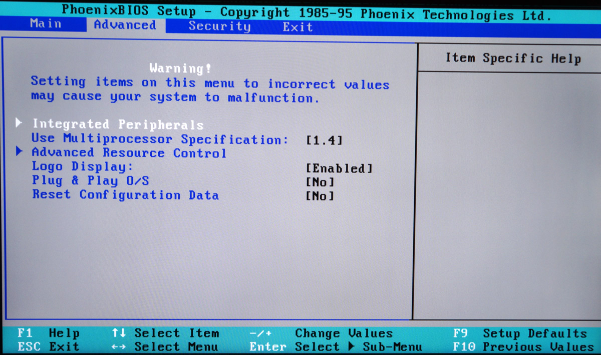
In the “Advanced” tab, you can select peripherals, MPS version 1.1 or 1.4 — this is the default, the logo is displayed on the initial screen and at the end the configuration is reset. The last point is very useful if you have a dead battery, or it is completely absent, as the garbage can accumulate in the ROM chip and the BIOS can go crazy at startup, so this option just needs to be selected before the first start.
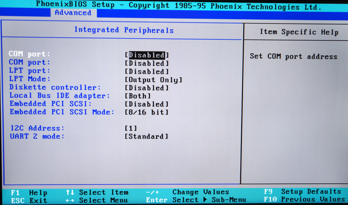
| In the “Integrated Peripherals” you can see the following options:
|
These are the standard settings for enabling / disabling ports and controllers, in one word, nothing unusual, as in the settings of system resources.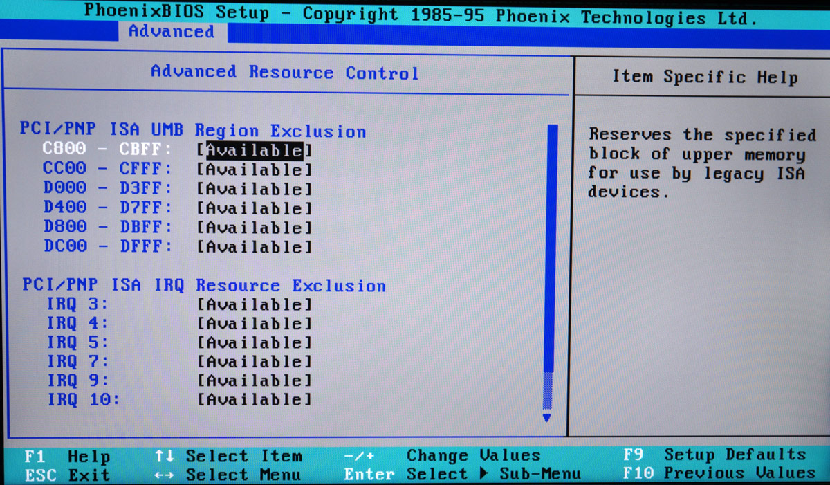 |
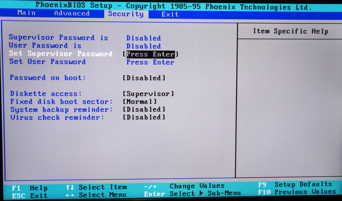
| In the next section, “Security”, you can set a password to enter the BIOS, enable bans on access to the floppy disk and scan for viruses. Here, everything is also standard.
|
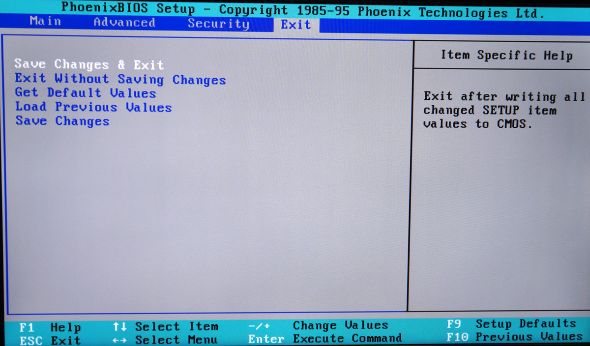
In the “Exit” section, a standard set of options is selected when exiting the BIOS Setup.
|
As you can see, the BIOS is quite standard, there is nothing supernatural in it. You will not find any settings responsible for raising the voltage on the processors, or choosing the multiplier or frequency of the FSB bus, this board dates back to the time when everything was done by hand.
Up next is the basic theory of operating 6 Pentium Pros in SMP and…Benchmarking and Overclocking!!!
Part 1: Mini-Mainframe at Home: The Story of a 6-CPU Server from 1997
Part 2: Mini-Mainframe at Home: Installing a Modern OS
Part 3: Mini-Mainframe at Home: The ALR 6×6 Hardware and BIOS
Part 4: Mini-Mainframe at Home: Benchmarks and Overclocking